Satellite receiver system

a satellite receiver and receiver technology, applied in the field of satellite receivers, can solve the problems of fading signal, adversely affecting the quality of received signals, and limited styling flexibility of vehicle manufacturers, so as to reduce the impact of fading and the possibility of reception mutes, eliminate aesthetic distractions, and increase styling flexibility

Active Publication Date: 2006-08-31
APTIV TECH LTD
View PDF6 Cites 31 Cited by
  • Summary
  • Abstract
  • Description
  • Claims
  • Application Information

AI Technical Summary

Benefits of technology

[0006] The present invention permits increased styling flexibility by providing a system that uses two or more antenna placed in different locations and switching diversity techniques to present the SDARS receiver with an antenna equivalent to an ideally placed, unobstructed antenna, thereby reducing the impacts of fading and the possibility of reception mutes. In general, two or more antennae are placed in electrically “diverse” positions which need not satisfy the above-mentioned line-of-sight placement criteria. These antennae may be buried in window glass, side mirrors, or otherwise “invisibly” located to eliminate aesthetic distractions, thereby improving the manufacturer's styling flexibility. The SDARS receiver is configured to intelligently select the stronger of the two or more signals received by the two or more antennae according to one or more of a variety of diversity algorithms.

Problems solved by technology

In mobile applications, such as receivers used in vehicles, the high variability of the reception environment results in various conditions that can adversely affect the quality of the received signals.
For example, multi-path fading, which is created when radio waves arrive at an antenna over routes of different lengths (e.g., some signals arrive directly from the transmission source, and others arrive after being reflected off buildings or other obstructions), causes signal fading because the various signals arriving at different times either reinforce or cancel each other.
Unfortunately, few locations on vehicles meet this placement criteria, and vehicle manufacturers have limited styling flexibility if they wish to accommodate SDARS systems.

Method used


Image

  • Satellite receiver system
  • Satellite receiver system
  • Satellite receiver system

Examples


first embodiment

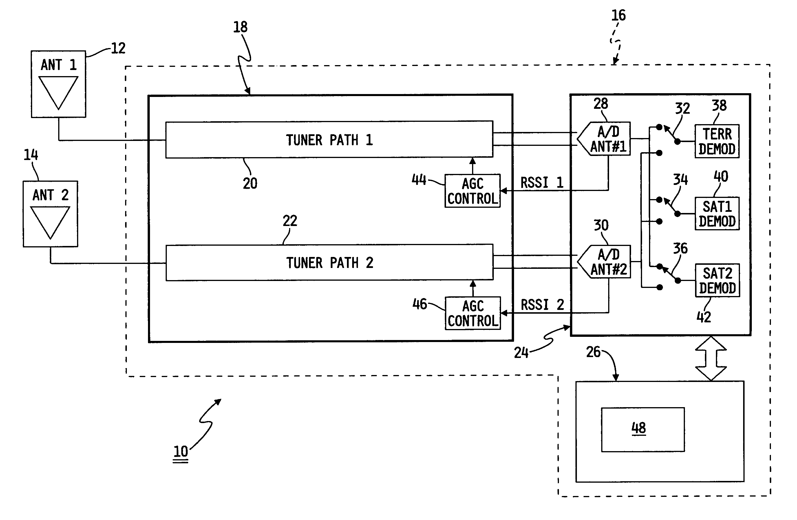
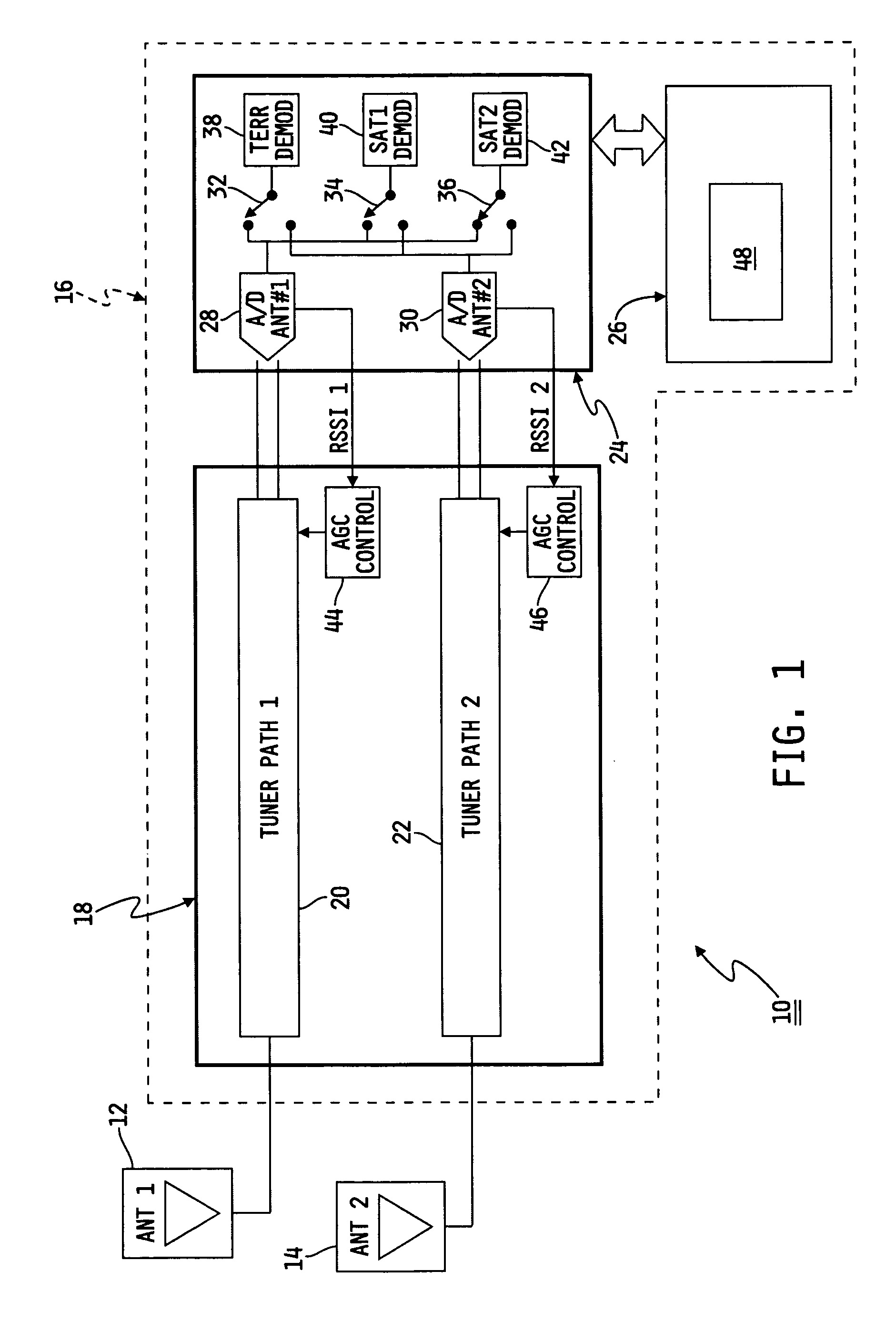
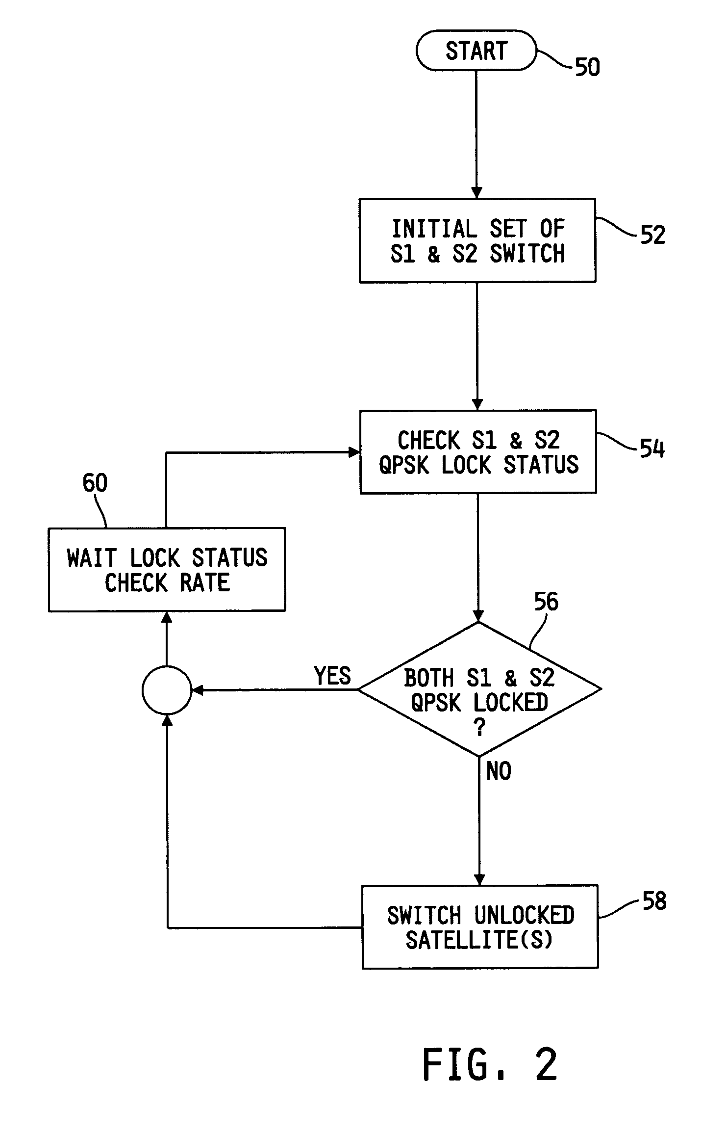
[0019] an algorithm for controlling satellite signal selection is depicted in flowchart form in FIG. 2. In general, each satellite demodulator 40, 42 includes a QPSK Lock Status indicator (a high level demodulator status flag indicating adequate synchronization) that can be used as a trigger to determine which of antenna 12 or antenna 14 currently provides a superior signal. More specifically, the QPSK Lock Status indicator is a rapidly updated hardware output pin of baseband 24 that is provided to microprocessor 26 and indicates whether receiver 16 is locked onto the satellite signal. If a signal received by one of the antennae 12, 14 is not locked, then a reduced amount of usable information is received by that antenna 12, 14.

[0020] After the algorithm of FIG. 2 is initiated at block 50, microprocessor 26 commands SAT1 demodulator 40 to cause switch 34 to connect SAT1 demodulator 40 to one of the two switch inputs (i.e., one provided by A / D converter 28 or one provided by A / D conv...

third embodiment

[0042] Referring now to FIG. 12, a dual baseband system 400 is shown. As shown, system 400 includes an R / S blocks combining block 428 instead of either a frame combining block 228 or a payload packet combining block 328. R / S blocks combining block 428 is coupled to each R / S decoder 214, 224 and provides an output to payload packet demux 216. In this embodiment, the smallest block of usable data (i.e., R / S blocks of 255 bytes of information) are used for comparison and to construct the resulting signal. Instead of comparing payload packets as in system 300, which each include two R / S blocks, both of which are discarded for the unselected payload packet, system 400 compares bitstreams on a R / S block-by-R / S block basis, and discards only the corrupt R / S blocks. Additionally, system 400 avoids the delay associated with the additional processing of payload packet demuxs 216, 226.

[0043] Referring now to FIGS. 13A and 13B, yet another single baseband embodiment of an algorithm for controll...


PUM


Abstract

An SDARS receiver for use with at least two antennae, each of which receives bitstreams from a first satellite, bitstreams from a second satellite, and bitstreams from a terrestrial repeater, including demodulators configured to switch between demodulating bitstreams from the satellites and to switch between demodulating bitstreams from the terrestrial repeater, and a processor coupled to the demodulators, the processor being configured to switch the demodulators according to a variety of algorithms.

Description

TECHNICAL BACKGROUND [0001] This application claims the benefit of U.S. Provisional Patent Application Ser. No. 60 / 657,184, filed Feb. 28, 2005, the disclosure of which is hereby expressly incorporated herein by reference.FIELD OF THE INVENTION [0002] The present invention generally relates to communication systems, and more particularly to satellite receivers employing switching / combining diversity techniques for use with satellite digital audio radio services (SDARS). BACKGROUND OF THE INVENTION [0003] SDARS is essentially a radio version of DBS systems such as Direct TV®, and provides audio (music and talk) and data broadcasting. SDARS systems, such as XM Radio® and Sirius®, provide approximately 100 digital quality radio channels of programming to the continental United States. Receivers have been developed for satellite radio reception from, in the case of XM Radio®, two geosynchronous satellites and a plurality of terrestrial repeaters used in areas with limited line-of-sight ...

Claims


Application Information

Patent Timeline
Patent Type & Authority Applications(United States)
IPC IPC(8): H04B1/16
CPCH04H40/90H04B7/18523
Inventor MARRAH, JEFFREY J.ZHANG, SHUPINGCRAMER, DOUGLAS A.DIAMOND, HARRY
Owner APTIV TECH LTD
Why Eureka
Try Eureka