Process for producing carbonyl fluoride
a carbonyl fluoride and carbon dioxide technology, applied in the preparation of carboxylic acid halides, organic compound preparations, organic chemistry, etc., can solve the problems of fear of fierce explosion and environmental impact, and achieve the effect of safely and easily producing carbonyl fluorid
- Summary
- Abstract
- Description
- Claims
- Application Information
AI Technical Summary
Benefits of technology
Problems solved by technology
Method used
Image
Examples
examples
[0070] The present invention is further described with reference to the following examples, but it should be construed that the invention is in no way limited to those examples.
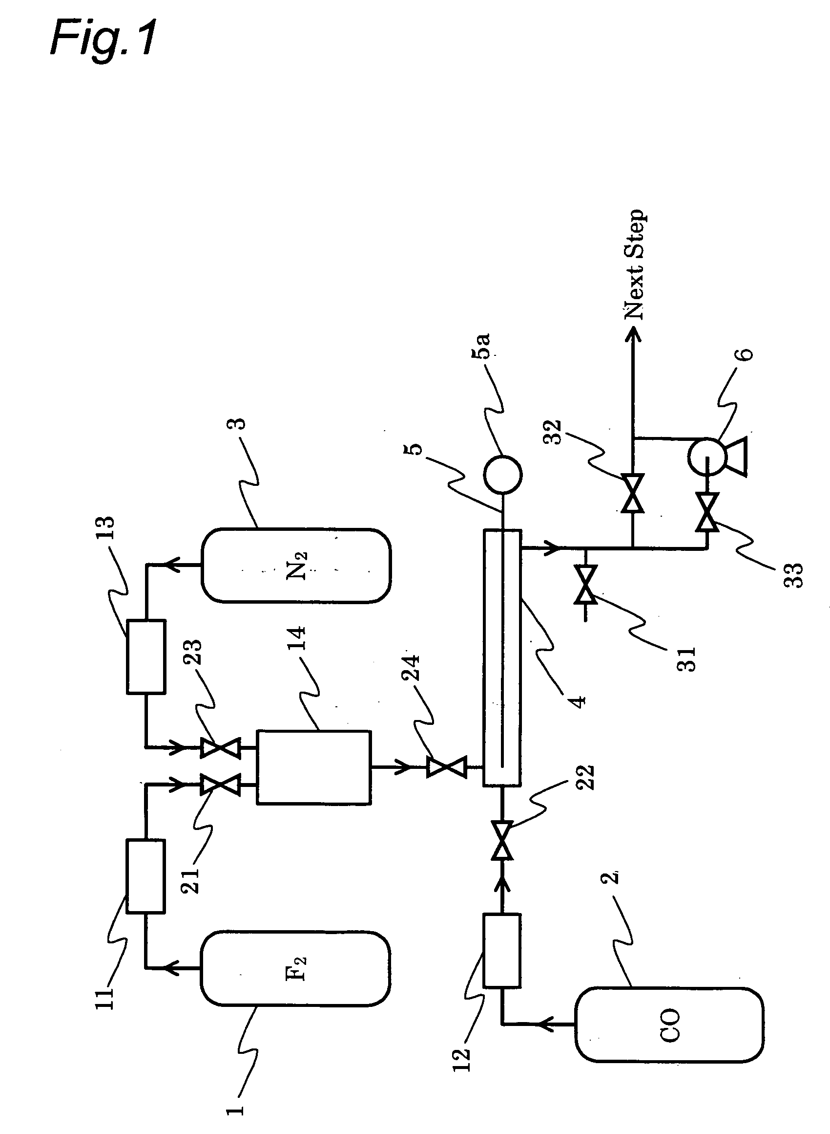
[0071] In the examples and the comparative examples, the carbonyl fluoride obtained was directly analyzed by connecting FTIR (available from Maidak Inc., model number: IGA-2000) to a carbonyl fluoride production apparatus shown in FIG. 1. To the connecting line between the carbonyl fluoride production apparatus and FTIR, a feed line for nitrogen gas for diluting was connected, and the resulting carbonyl fluoride was appropriately diluted with nitrogen, followed by analysis.
[0072] In the examples and the comparative examples, the yield of carbonyl fluoride and the reaction selectivity of CF4 were determined by the following formulas.
COF2 yield=[COF2] / [F2] (5)
CF4 selectivity=[CF4] / ([CF4]+[COF2]+[CO2]) (6)
examples 1-5
[0073] The pressure inside a nickel reactor (inner diameter 16.7 mm×length 300 mm) was reduced by means of a pressure reducing pump. Then, at a reactor internal pressure shown in Table 1, carbon monoxide (purity: 99.95%) and fluorine (purity: 99.9%) were each independently fed to the reactor at a flow rate of 30 sccm (CO / F2 (by mol): 1.0) to start the reaction at room temperature. As the temperature inside the reactor, a temperature at the meeting point of carbon monoxide and fluorine was measured. It was confirmed that the maximum temperature inside the reactor appeared at this meeting point. In Table 1, the reactor internal temperature in the steady state is set forth.
[0074] The resulting gas was appropriately diluted with nitrogen, and gas composition was analyzed by FTIR. The result is set forth in Table 1.
TABLE 1Ex. 1Ex. 2Ex. 3Ex. 4Ex. 5CO (sccm)3030303030F2 (sccm)3030303030CO / F2 (by mol)1.01.01.01.01.0Pressure (kPa)100.897.090.670.147.2Temperature (° C.)175117118118122COF2 ...
examples 6-8
[0075] The pressure inside a nickel reactor (inner diameter 16.7 mm×length 300 mm) equipped with a cooling system was reduced by means of a pressure reducing pump. Then, under the conditions of a reactor internal pressure of 100.1 kPa, carbon monoxide (purity: 99.95%) and fluorine (purity: 99%) were each independently fed to the reactor at flow rates shown in Table 2 to start the reaction at room temperature. As the temperature inside the reactor, a temperature at the meeting point of carbon monoxide and fluorine was measured. It was confirmed that the maximum temperature inside the reactor appeared at this meeting point. In Table 2, the reactor internal temperature in the steady state is set forth.
[0076] The resulting gas was appropriately diluted with nitrogen, and gas composition was analyzed by FTIR. The result is set forth in Table 2.
TABLE 2Ex. 6Ex. 7Ex. 8CO (sccm)306090F2 (sccm)303030CO / F2 (by mol)1.02.03.0Pressure (kPa)100.1100.1100.1Temperature (° C.)185160130COF2 yield (...
PUM
 Abstract
Description
Claims
Application Information
 - R&D
- Intellectual Property
- Life Sciences
- Materials
- Tech Scout
- Unparalleled Data Quality
- Higher Quality Content
- 60% Fewer Hallucinations
Browse by: Latest US Patents, China's latest patents, Technical Efficacy Thesaurus, Application Domain, Technology Topic, Popular Technical Reports.
© 2025 PatSnap. All rights reserved.Legal|Privacy policy|Modern Slavery Act Transparency Statement|Sitemap|About US| Contact US: help@patsnap.com


