[0011] As stated hereinabove, according to the present invention, the joint moments of the legs can be estimated by using the values of the motion states of the rigid elements in the body coordinate system or the rigid equivalent parts of the two-legged walking mobile body corresponding to the rigid elements, thereby enabling a reduction in arithmetic
processing using the tilt information of the two-legged walking mobile body (information on a degree of tilt relative to the vertical direction or the horizontal direction of a certain region of the two-legged walking mobile body). As a result, the
estimation accuracy of the joint moments of the legs can be enhanced.
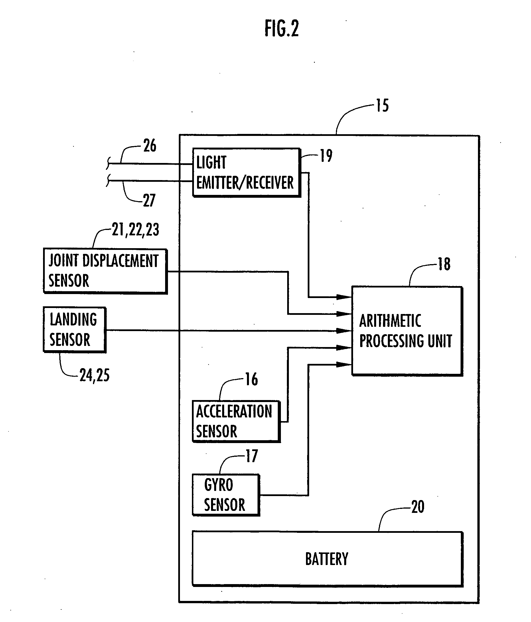
[0013] In this invention, the acceleration sensor can be attached basically to any rigid equivalent part of the two-legged walking mobile body, though it is preferably attached to the rigid equivalent part of the two-legged walking mobile body corresponding to the rigid element to which the body coordinate system is fixed (a second invention). More specifically, if the acceleration sensor is attached to a region other than the rigid equivalent part of the two-legged walking mobile body corresponding to the rigid element to which the body coordinate system is fixed, there is a need to calculate an acceleration vector of the rigid equivalent part corresponding to the rigid element to which the body coordinate system is fixed by using a displacement or the like of the joint of the two-legged walking mobile body from the acceleration vector of the attached region. On the other hand, if the acceleration sensor is attached to the rigid equivalent part corresponding to the rigid element to which the body coordinate system is fixed like the second invention, the positional relationship between the origin of the body coordinate system and the acceleration sensor is fixed and thus the value in the body coordinate system of the acceleration vector of the origin of the body coordinate system can be grasped from the output of the acceleration sensor without using the displacement of the joint of the two-legged walking mobile body. This enables an enhancement of the accuracy of the grasped value in the body coordinate system of the acceleration vector of the origin of the body coordinate system.
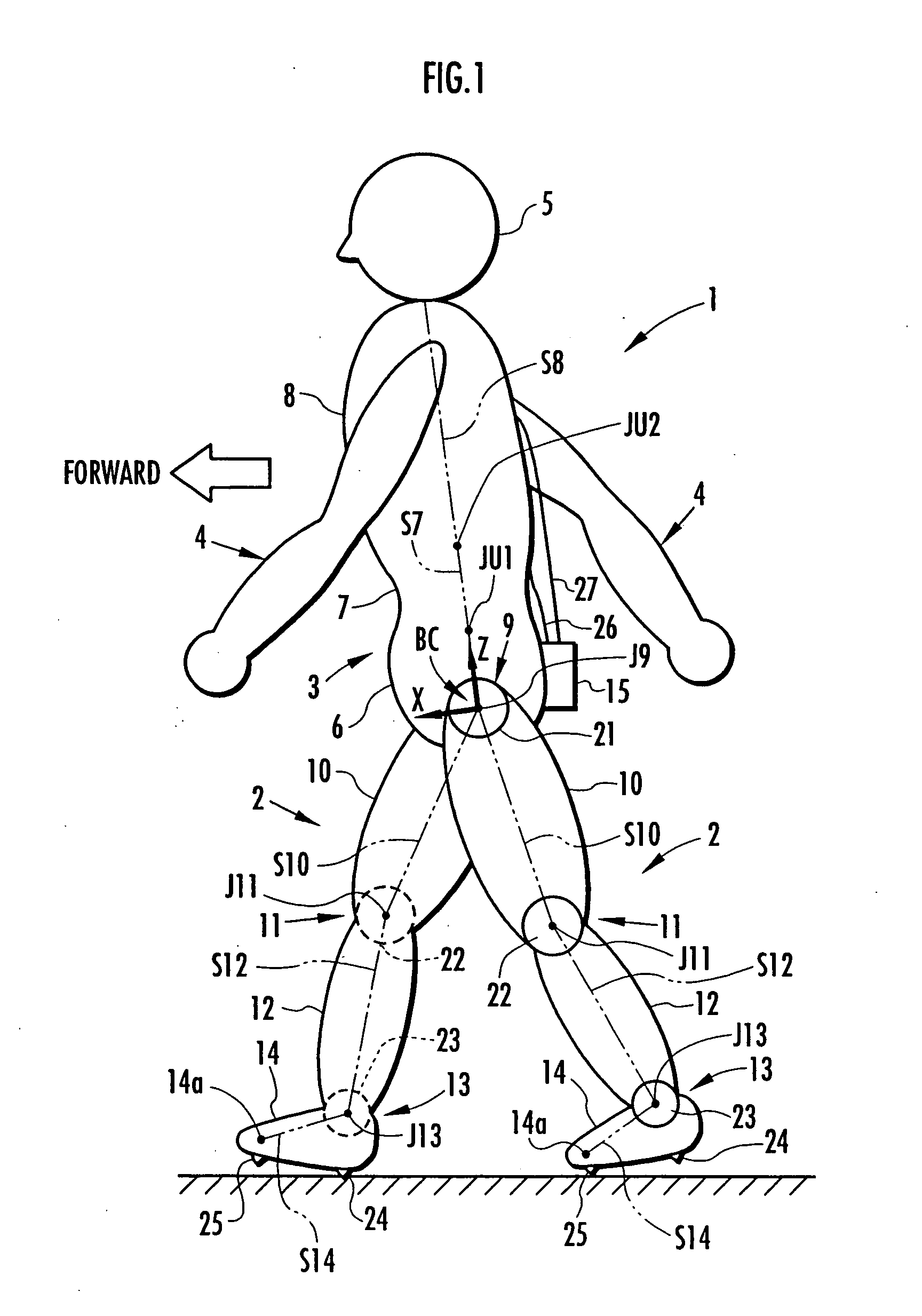
[0014] Moreover, in the second invention, the rigid element to which the body coordinate system is fixed is preferably a rigid element connecting a pair of joint elements corresponding to a pair of hip joints of the two-legged walking mobile body (a third invention). More specifically, the rigid element connecting the pair of joint elements corresponding to the pair of hip joints of the two-legged walking mobile body corresponds to the
waist of the two-legged walking mobile body and the
waist relatively less moves during walking of the two-legged walking mobile body in general. Accordingly, the output of the acceleration sensor can be relatively stabilized by reducing abrupt changes in the outputs of the acceleration sensor and it further enables an enhancement of the accuracy of the grasped value in the body coordinate system of the acceleration vector of the origin of the body coordinate system.
[0021] When estimating the position vector of the point of application of the floor reaction force in this manner, there is a need to grasp the tilt angle to the vertical direction of the rigid equivalent part of the two-legged walking mobile body corresponding to the rigid element to which the body coordinate system is fixed by using a sensor for detecting tilt angles (an
angular velocity sensor or a
tiltmeter). In this invention, however, the tilt angle may be used only for estimating the point of application of the floor reaction
force vector, thus reducing the arithmetic operations using the tilt angle to the minimum. Therefore, even if the tilt angle has an error, the accumulation of arithmetic errors can be held to the minimum, thus securing a sufficiently high accuracy in estimating a
joint moment. Moreover, the pressure distribution sensor need not be disposed at the bottom of the foot apt to receive a relatively large load instantaneously, which leads to an
advantage in durability of the apparatus configuration for estimating joint moments.
[0028] According thereto, in the state where only the
toe-side portion of the foot of the landing leg is determined to be in contact with the ground, the position located the
vertical distance between the
ankle joint and the metatarsophalangeal joint apart from the vertical position of the
ankle joint of the leg downward in the vertical direction is estimated as the vertical position of the point of application of the floor reaction force vector. As a result, the estimation accuracy can be increased in the vertical position of the point of application of the floor reaction force vector.
[0029] In the inventions described hereinabove, the value of the floor reaction force vector and the value of the position vector of the point of application of the floor reaction force vector respectively grasped in the third step and the fourth step are preferably three-dimensional values (a ninth invention). According thereto, the value of the floor reaction force vector and the value of the position vector of the point of application of the floor reaction force vector are grasped according to spatial behaviors of the two-legged walking mobile body, thereby increasing the estimation accuracy of the joint moments estimated based on them.

