Medical diagnostic system service method and apparatus

Inactive Publication Date: 2006-08-31
ACCARDI KENNETH LAWRENCE +7
View PDF9 Cites 21 Cited by
  • Summary
  • Abstract
  • Description
  • Claims
  • Application Information

AI Technical Summary

Benefits of technology

[0009] The present invention provides an interactive servicing technique for medical diagnostic equipment designed to respond to these needs. The technique offers a straightforward and user-friendly environment for identifying and requesting service for potential problems occurring at the scanner, which may be either recurring in nature or intermittent. The technique may be applied on a variety of scanner modalities, and offers a uniform interface, platform and system architecture across modalities. Thus, the system may be easily adapted to permit a remote service center to provide high quality service to various diagnostic equipment regardless of the modality, model or even the manufacturer. Moreover, a wide array of service fu

Problems solved by technology

The scanners are provided with only limited functionality in the ability to identify and define service needs.
Even where the scanners have permitted some limited ability to contact networked service providers, intermittent conditions indicative of a potentially serviceable problem may cease by the time the service provider is contacted or recontacts the scanner after a service call.
Currently available service systems do not permit such interactive exchanges.
In addition to the foregoing drawbacks, conventional scanners are not suitably adapted to support user-friendly, scanner-based service exchanges.
User interfaces in such scanners typically only permit limited access to service information, and do not provide a particularly useful interface for identifying and defining serviceable conditions as they occur.
Moreover, software platforms and interfaces in conventional scanners are not suitable for interaction with

Method used


Image

  • Medical diagnostic system service method and apparatus
  • Medical diagnostic system service method and apparatus
  • Medical diagnostic system service method and apparatus

Examples


Embodiment Construction

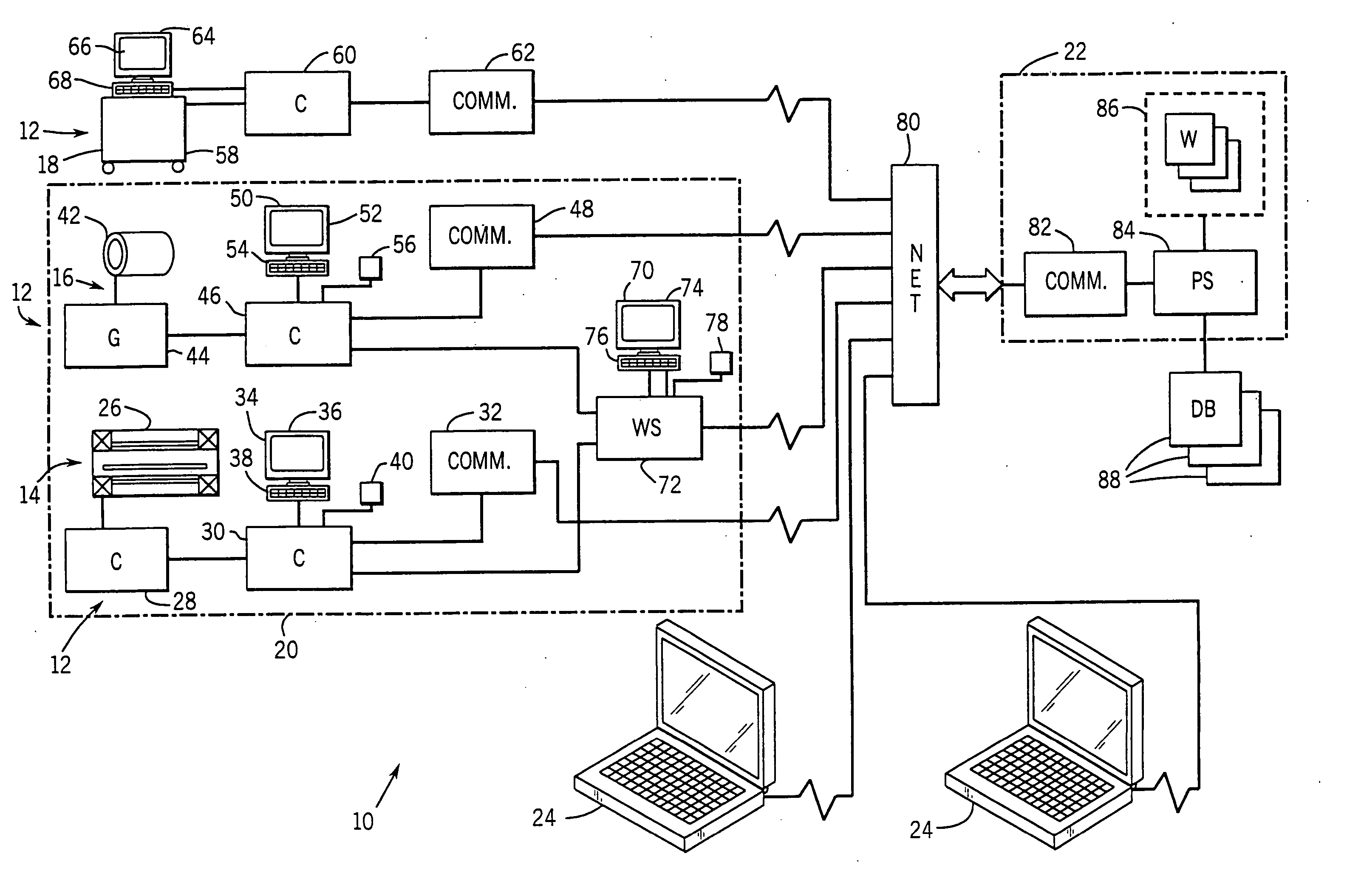
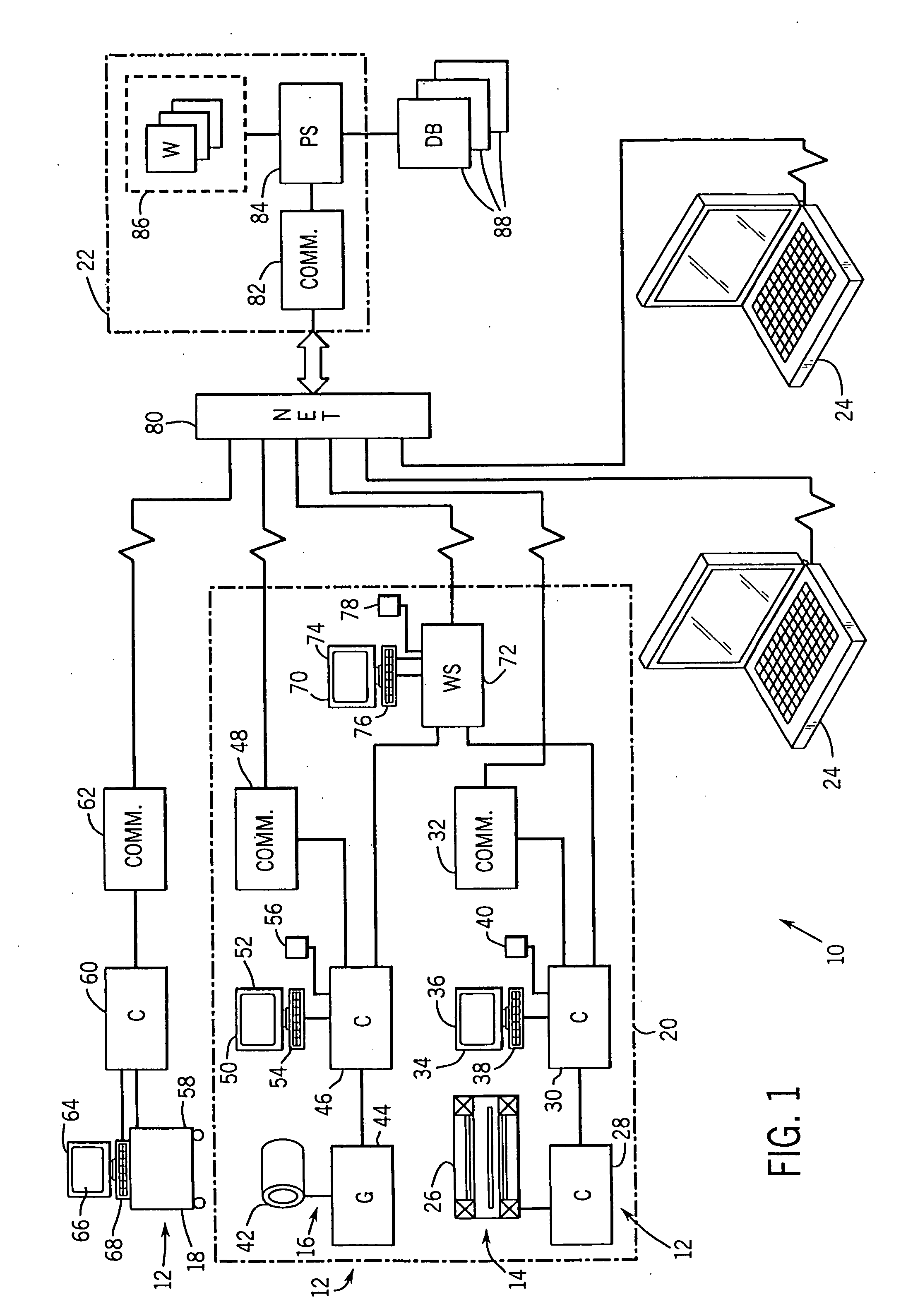
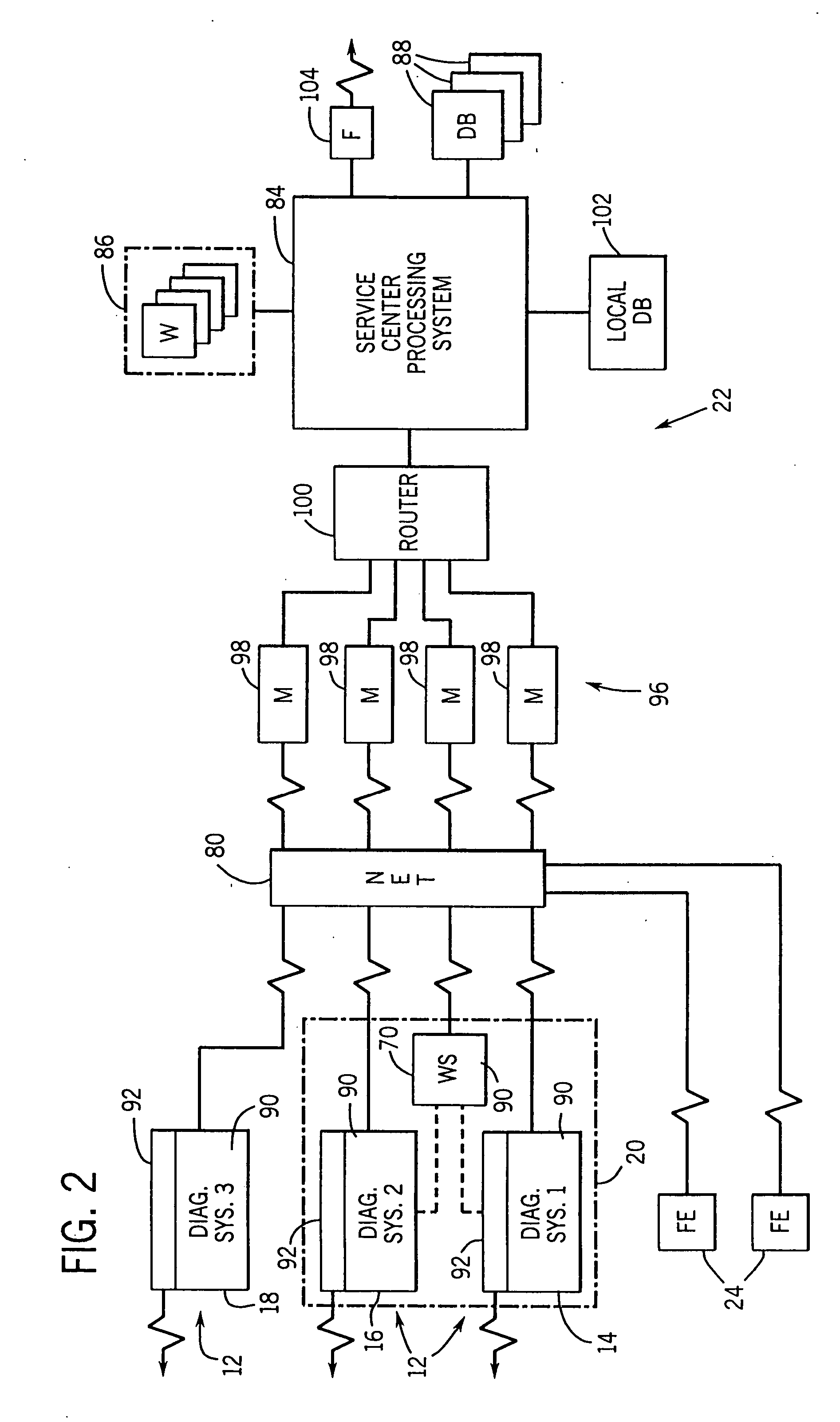
[0029] Turning now to the drawings, and referring first to FIG. 1, a service system 10 is illustrated for providing remote service to a plurality of medical diagnostic systems 12. In the embodiment illustrated in FIG. 1, the medical diagnostic systems include a magnetic resonance imaging (MRI) system 14, a computed tomography (CT) system 16, and an ultrasound imaging system 18. The diagnostic systems may be positioned in a single location or facility, such as a medical facility 20, or may be remote from one another as shown in the case of ultrasound system 18. The diagnostic systems are serviced from a centralized service facility 22. Moreover, a plurality of field service units 24 may be coupled in the service system for transmitting service requests, verifying service status, transmitting service data and so forth as described more fully below.

[0030] In the exemplary embodiment of FIG. 1, several different system modalities are provided with remote service by the service facility...


PUM


Abstract

A system is provided for remotely servicing medical diagnostic systems. The diagnostic systems may include a range of modalities and system types. A remote service facility may be contacted by the diagnostic systems, or may contact the diagnostic systems via a network link. Service requests, messages, protocols, data and log files, and so forth, may be transmitted between the diagnostic systems and the service facility. The service requests are handled by the service facility interactively with the medical diagnostic systems. The diagnostic systems are thereby apprised of the status of service requests, service reports, and so forth. A uniform interface and platform are provided for facilitating interactive communications of service requests and data between the diagnostic systems and the service facility.

Description

FIELD OF THE INVENTION [0001] The present invention relates generally to the field of medical diagnostic and imaging systems. More particularly, the invention relates to interactive servicing of such systems, such as via remote service facilities, in which system configurations, image data and other files, protocols, service requests, reports and other useful information can be exchanged interactively between a remote service facility and the diagnostic system. BACKGROUND OF THE INVENTION [0002] Medical diagnostic and imaging systems are ubiquitous in modern health care facilities. Such systems provide valuable tools for identifying, diagnosing and treating physical conditions and greatly reduce the need for surgical diagnostic intervention. In many instances, final diagnosis and treatment proceed only after an attending physician or radiologist has complemented conventional examinations with detailed images of relevant areas and tissues via one or more imaging modalities. [0003] Cu...

Claims


Application Information

Patent Timeline
IPC IPC(8): G06F15/173
CPCG06F19/327G16H40/20
Inventor ACCARDI, KENNETH LAWRENCEBABULA, DEBORAH ANNGESIOR, GEORGE PETERHUMMEL, HENRY JOHN JR.KORITZINSKY, IANNE MAE HOWARDSMCOLASH, SCOTT MATTTZORTZOS, GEORGEZETTEL, HUBERT ANTHONY
Owner ACCARDI KENNETH LAWRENCE
Why Eureka
Try Eureka