Self-cleaning plasticizing venting and extruding apparatus by co-rotating non-twin multi-screws and method thereof

a venting and extruding apparatus technology, applied in the field of plasticizing venting and extruding polymeric materials, can solve the problems of insufficient and achieve good plasticizing and mixing

Active Publication Date: 2013-04-11
GUANGDONG IND TECHN COLLEGE
View PDF8 Cites 5 Cited by
  • Summary
  • Abstract
  • Description
  • Claims
  • Application Information

AI Technical Summary

Benefits of technology

[0004]The primary purpose of the present invention is to overcome the defects and deficiencies in the prior art, to provide a self-cleaning plasticizing venting and extruding apparatus by co-rotating non-twin multi-screws having good plasticizing and mixing effects and having a self-cleaning effect during the polymeric materials processing process.

Problems solved by technology

Although this structure can preliminarily solve the problems such as the poor mixing property, the poor self-cleaning property, and the poor venting effect, etc., during the material processing process, there are still the following defects: (1) as the shapes of the two screws are the same, there are consistency (symmetry) therebetween, so that there is a consistency in the geometrical space through which the fluids pass during they proceeding along the two screws, there is an absence in the conversion between the geometric shapes of the spaces for processing the fluids, the reorientation effect of the interface during the shearing process is attenuated, and the mixing effect is limited, especially, that most of the fluid mixing in the core region of the screw channels is still laminar mixing, and the interface is increased linearly with time, (2) the studies have shown that the co-rotating twin screws can only make an effective mixing effect on the surface layer fluid near the wall region, especially in the engaging region, the effect is extraordinarily obvious, in general, there is still an extremely large possibility for improvement in the fluid mixing in the core regions.

Method used


Image

  • Self-cleaning plasticizing venting and extruding apparatus by co-rotating non-twin multi-screws and method thereof
  • Self-cleaning plasticizing venting and extruding apparatus by co-rotating non-twin multi-screws and method thereof
  • Self-cleaning plasticizing venting and extruding apparatus by co-rotating non-twin multi-screws and method thereof

Examples


embodiment 1

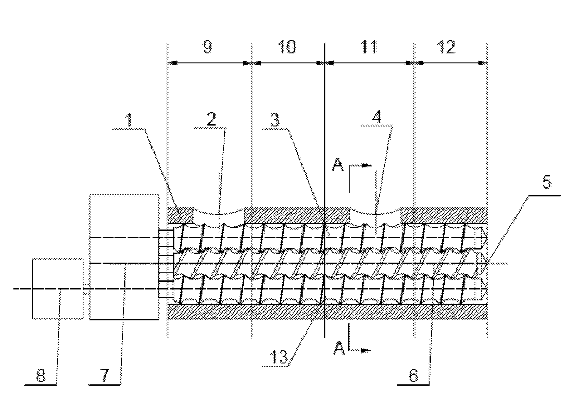
[0078]As shown in FIG. 1, the self-cleaning plasticizing venting and extruding apparatus by co-rotating non-twin multi-screws comprises a screw mechanism, a barrel 1, a feeding port 2, a venting port 4, a discharging port 5, and a driving mechanism, wherein said driving mechanism is provided at the ends of the barrel 1 respectively, and is connected to the screw mechanism; said screw mechanism is provided inside the barrel 1, and placed horizontally, and the inner section of the barrel 1 are divided into a solid transporting zone 9, a melting zone 10, a venting zone 11 and a compounding and extruding zone 12; said feeding port 2 is provided above the barrel 1 of the solid transporting zone 9, said venting port 4 is provided above the barrel 1 of the venting zone 11, both the feeding port 2 and the venting port 4 are communicated with the barrel 1; said discharging port 5 is provided at the end of the barrel 1, said screw mechanism comprises a central screw 6 and two uniform shaped l...

embodiment 2

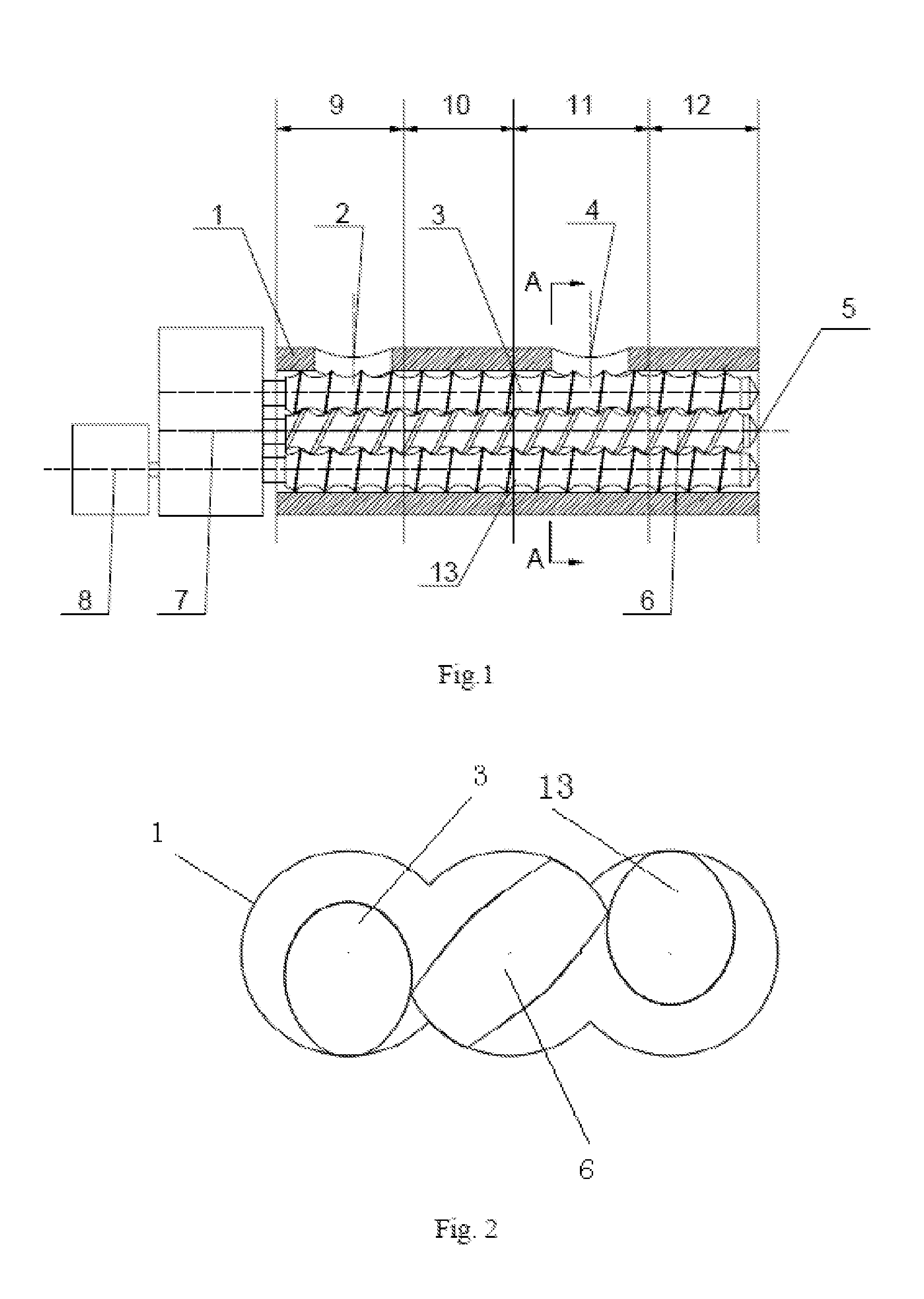
[0094]The present embodiment has the same structure as that in embodiment 1, except the following features: as shown in FIG. 3, the phase angle difference between the positions of said left screw 3 and right screw 13 is 180°, ie., the shape of the cross-section of said left screw 3 is the same as the curve shape formed after the cross-section of the right screw 13 is rotated counterclockwise by 180° along the center point of the cylinder groove of the barrel corresponding to the central screw. With the center points of the cylinder grooves of the barrel corresponding to the central screw 6 and each of the lateral screws respectively as poles, and the rays elicited horizontally rightwards from the poles (ie., in the orthogonal coordinate system, the rays in the positive direction of X axis of the connecting line through the center points of the cylinder grooves of the barrel) as polar axes, the shape curve of the cross-section of said central screw 6 meets that:

when0°≤θ≤23°,ρ(θ)=(0.3...

embodiment 3

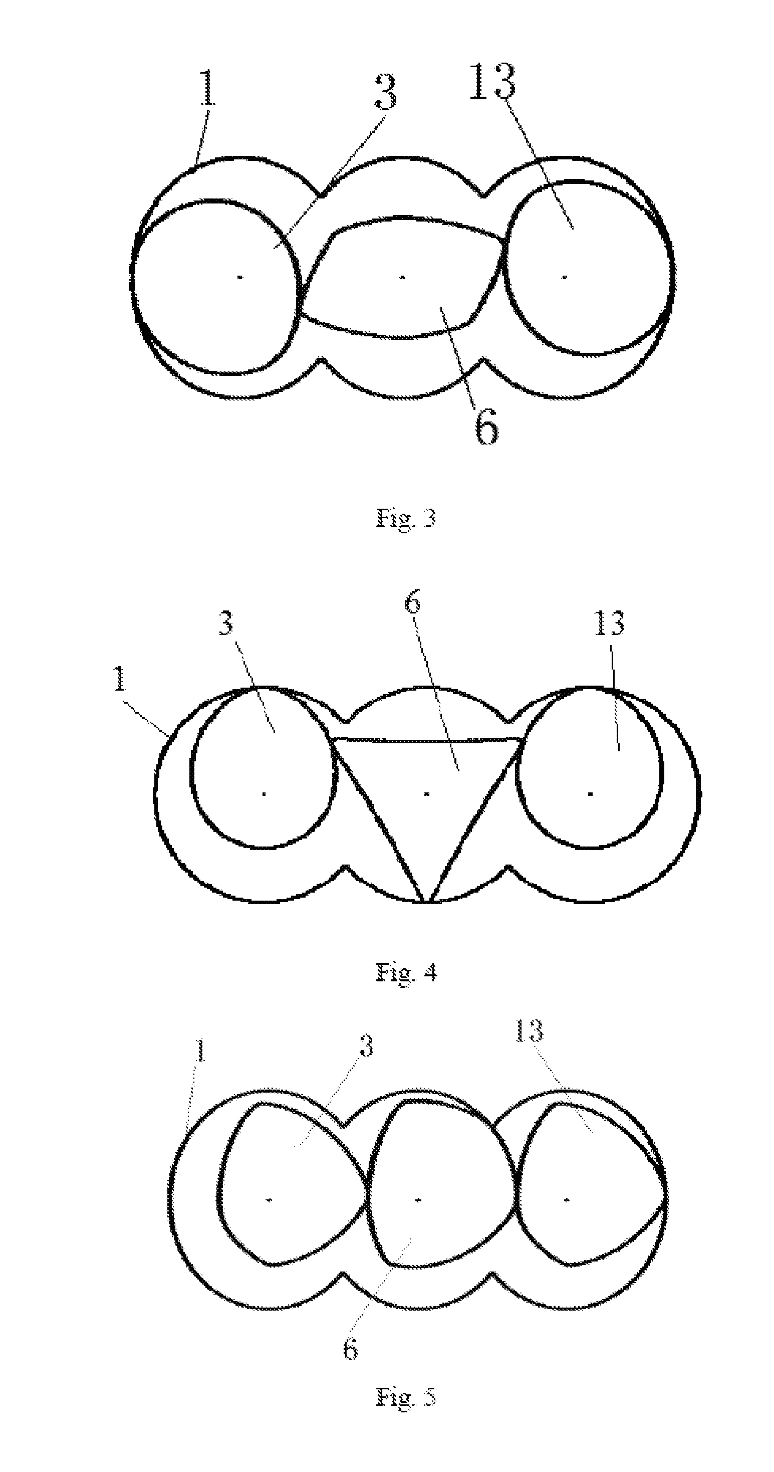
[0099]The present embodiment has the same structure as that in embodiment 1, except the following features: as shown in FIG. 4, the phase angle difference between the positions of said left screw 3 and right screw 13 is 0°, ie., the shape of the cross-section of said left screw 3 is the same as the curve shape of the cross-section of the right screw 13; with the center points of the cylinder grooves of the barrel corresponding to the central screw 6 and each of the lateral screws respectively as poles, and the rays elicited horizontally rightwards from the poles (ie., in the orthogonal coordinate system, the rays in the positive direction of X axis of the connecting line through the center points of the cylinder grooves of the barrel) as polar axes, the shape curve of the cross section of said central screw 6 meets that:

when0°≤θ≤27°,ρ(θ)=(0.28995+0.0029θ+0.000104586θ2+1.35828×10⁻⁶θ3-6.80098×10⁻⁸θ4+3.45975×10⁻⁹θ5)D0;when27°≤θ≤36°,ρ(θ)=(0.4847+0.01065(θ-27)-0.00186(θ-27)2+5.1776×10⁻⁶(...


PUM

PropertyMeasurementUnit
peak angleaaaaaaaaaa
phase angleaaaaaaaaaa

Abstract

A self-cleaning plasticizing venting and extruding apparatus by co-rotating non-twin multi-screws and a method thereof are provided, said apparatus comprises a screw mechanism, a barrel (1), a feeding port (2), a venting port (4), a discharging port (5), and a driving mechanism, said screw mechanism comprises non-uniform shaped central screw (6) and lateral screws (3,13), the axis of the central screw (6) is coincided with that of the barrel (1), and the lateral screws are provided on both sides of the central screw (6) respectively and engaged with the central screw (6); the contour lines of the threads of said central screw (6) and said lateral screws (3,13) are tangent to the inner wall of the barrel (1) ; and said driving mechanism is connected to the central screw (6) and the lateral screws (3,13) respectively. Each of the screws in the present invention uses an asymmetrical flow channel geometrical shape, so that the flow spaces for materials have an asymmetry, the compounding intensity and effectiveness are overall enhanced; the dispersion and mixing effects are extremely excellent, and a self-cleaning effect is generated, so that it is especially suitable for processing nano-materials in high yield.

Description

TECHNICAL FIELD[0001]The present invention relates to a processing technique for plasticizing, venting and extruding polymeric materials, particularly to a self-cleaning plasticizing venting and extruding apparatus by co-rotating non-twin multi-screws and method thereofBACKGROUND ART[0002]The co-rotating twin-screw extruders have been widely applied in the fields such as filling, modifying, blending, and reactive extruding polymeric materials, etc. The principle is that: the structures of the two screws are identical, when assembled, there is a certain phase angle between them, the centerline distance is related to the number of screw tips and the peak angle, and the rotation speeds of the two screws are the same during the processing process. To achieve the self-cleaning effect during the processing process, from the viewpoint of relative movement, the two screws keep constant in the phase therebetween, contact and make a translational movement each other. Although this structure c...

Claims


Application Information

Patent Timeline
Patent Type & Authority Applications(United States)
IPC IPC(8): B29C47/08B29C48/405B29C48/425B29C48/64B29C48/76
CPCB29C47/0881B29C48/2715B29C48/42B29C48/64B29C48/65B29C48/402B29C48/425B29C48/765B29C48/767B29C48/2517B29C48/04B29C48/682B29C48/683B29C48/405B29B7/489B29B7/485
Inventor XU, BAIPINGWANG, MEIGUIHE, LIANGKONG, PINGCHEN, JINWEI
Owner GUANGDONG IND TECHN COLLEGE
Why Eureka
Try Eureka