Inkjet recording head
a recording head and inkjet technology, applied in printing and other directions, can solve the problems of increasing the tendency of adhesive to protrude into the ink channel, affecting the flow of ink in the channel portion, and causing air bubbles, etc., to achieve high-density nozzle arrangement and high-quality printing
- Summary
- Abstract
- Description
- Claims
- Application Information
AI Technical Summary
Benefits of technology
Problems solved by technology
Method used
Image
Examples
first embodiment
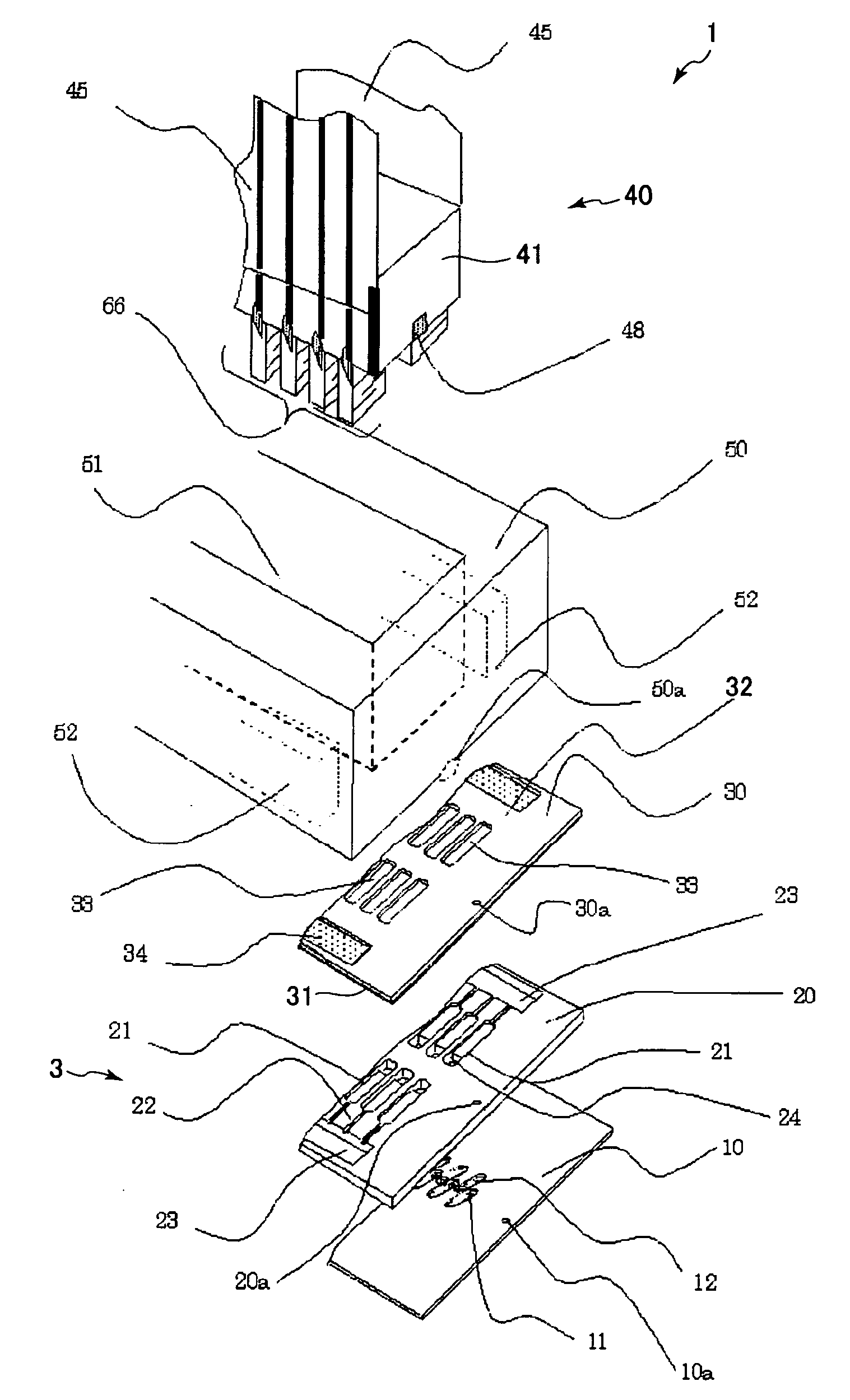
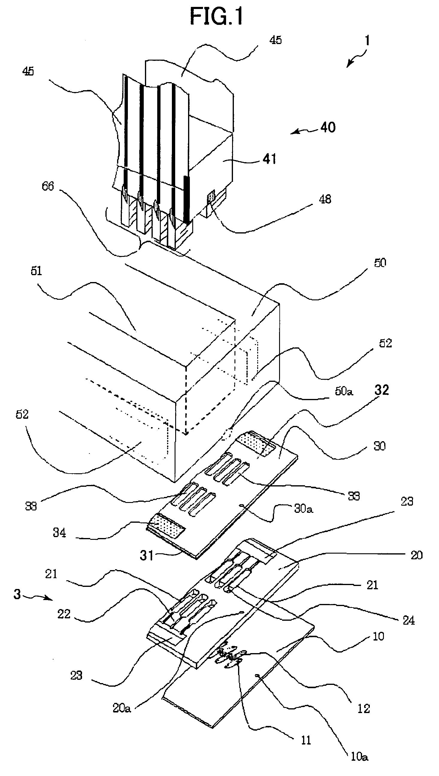
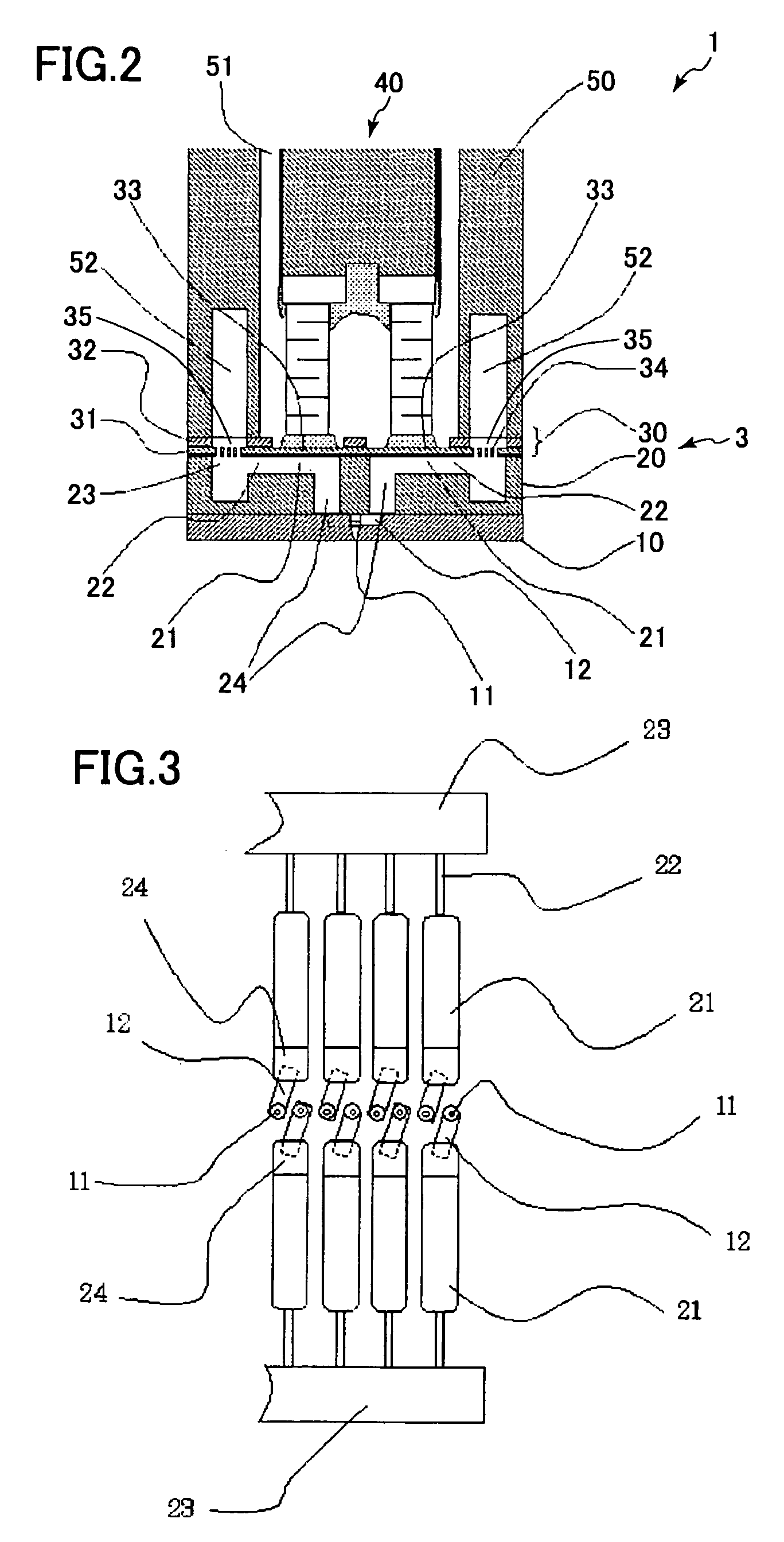
[0029] An inkjet recording head according to the present invention will be described with reference to FIGS. 1 through 5C.
[0030] As shown in FIG. 1, a recording head 1 includes a channel substrate 3, a piezoelectric actuator 40, and a housing 50.
[0031] The channel substrate 3 includes a nozzle plate 10, a chamber plate 20, and a diaphragm plate 30 that are superposed and fixed together.
[0032] The nozzle plate 10 includes a plurality of nozzles 11 (see FIG. 3) for ejecting ink droplets, a plurality of connecting channels 12 (see FIG. 3) in communication with the nozzles 11 and pressure chambers 21 described later, and positioning holes 10a formed each side of the nozzle plate 10 in a longitudinal direction thereof.
[0033] The nozzle plate 10 is configured of a silicon single-crystal substrate with a (110) plane. The nozzles 11, the connecting channels 12, and the positioning hole 10a are formed in the nozzle plate 10 by dry etching. As shown in FIG. 2, steps are formed in the nozzl...
second embodiment
[0056] The inkjet recording head includes a plurality of connecting channels 12a formed in the nozzle plate 10. The connecting channels 12a extend alternately in opposite directions and are formed parallel to the direction orthogonal to the row of nozzles 11. Each connecting channel 12a extends along a first centerline L1 passing through a center of each connecting channel 12a in a width direction thereof and extending in the longitudinal direction of each connecting channel 12a. A one end of each connecting channels 12a is in communication with the respective nozzles 11.
[0057] The inkjet recording head according to the second embodiment also includes a plurality of through-holes 24a and a plurality of pressure chambers 21a formed in the chamber plate 20. Each of through-holes 24a is in communication with the respective connecting channels 12a. The pressure chambers 21a are arranged in two rows, one on either side of the row of nozzles 11. The pressure chambers 21a of one row are p...
third embodiment
[0060] The chamber plate 20 is formed by anisotropic wet etching of a silicon single-crystal substrate with a (110) surface. As shown in FIG. 8, planes A, B, and C emerge when performing anisotropic wet etching of silicon single-crystal substrate with the (110) surface. Here, anisotropic wet etching is used to form (111) planes (planes A and B in FIG. 8) orthogonal to the (110) plane, and to produce depressed areas in the shape of parallelograms (pressure chambers 21b and through-holes 24b) in which the planes A correspond to sides 16 and 17 and the planes B correspond to sides 18 and 19 in FIG. 7. This technique achieves an extremely high precision during the molding process.
[0061] The pressure chambers 21b formed in the chamber plate 20 communicate with the connecting channels 12a via corner parts of the through-holes 24b forming an acute angle in the parallelogram. By forming the nozzle plate 10 through dry etching and the chamber plate 20 through anisotropic wet etching in this...
PUM
 Abstract
Description
Claims
Application Information
 - R&D
- Intellectual Property
- Life Sciences
- Materials
- Tech Scout
- Unparalleled Data Quality
- Higher Quality Content
- 60% Fewer Hallucinations
Browse by: Latest US Patents, China's latest patents, Technical Efficacy Thesaurus, Application Domain, Technology Topic, Popular Technical Reports.
© 2025 PatSnap. All rights reserved.Legal|Privacy policy|Modern Slavery Act Transparency Statement|Sitemap|About US| Contact US: help@patsnap.com


