
Backlight module for LCD

Active Publication Date: 2006-09-07
INNOLUX CORP
View PDF3 Cites 11 Cited by
  • Summary
  • Abstract
  • Description
  • Claims
  • Application Information

AI Technical Summary

Benefits of technology

[0009] A backlight module for a liquid crystal display (LCD) of the present invention provides a plane light source with enhanced brightness and uniformity.
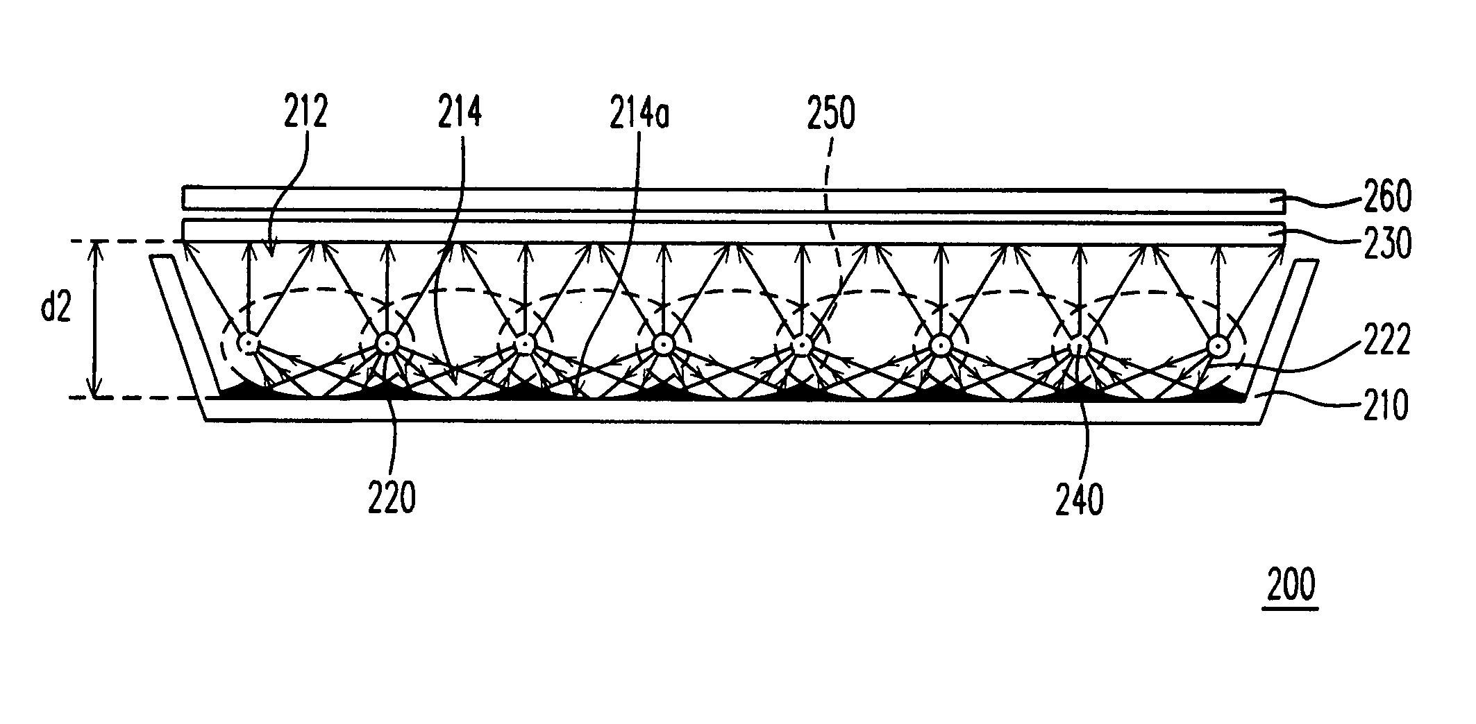
[0016] The backlight module as provided has a plurality of elliptic reflective curved surfaces formed on a bottom surface thereof. The real light sources are disposed on focal points of alternate elliptic reflective curved surfaces. Therefore, a part of light emitted from the real light sources will be reflected to the elliptic reflective curved surfaces to form a plurality of virtual light sources. In other words, a uniform plane source based on a plurality of real light sources and virtual light sources is obtained to provide more efficient luminescence.

Problems solved by technology

Although the conventional cathode ray tube (CRT) display has the persistent advantage, the structure of the internal electronic cavity results in a large volume of the display and causes great radiation to hurt human's eyes.
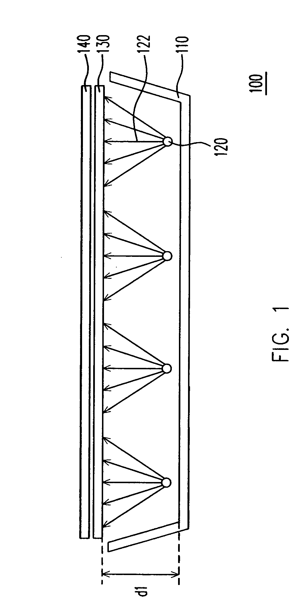
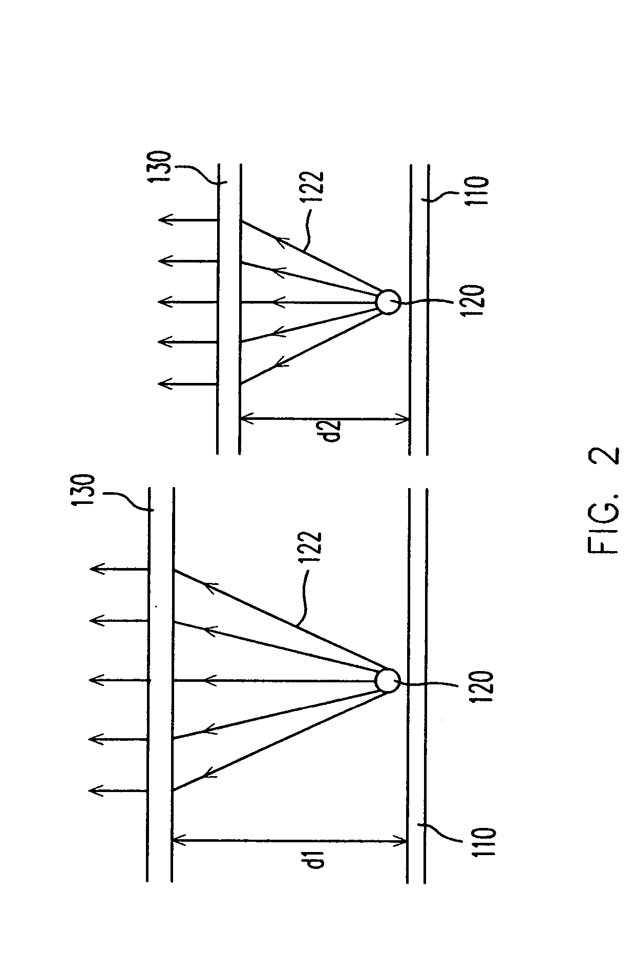
Therefore, the uniformity of the plane light source is normally poor.

Method used


Image

  • Backlight module for LCD
  • Backlight module for LCD
  • Backlight module for LCD

Examples


Embodiment Construction

[0022]FIG. 3 shows an embodiment of a backlight module, and FIG. 4 shows a perspective drawing of FIG. 3. Referring to FIGS. 3 and 4, the backlight module 200 is a direct-type backlight module. The backlight module 200 includes a light box 210 and a plurality of real light sources 220. The light box 210 has an opening 212 and a plurality of parallel grooves 214 recessed from a bottom surface thereof. The light box 210 further comprises a plurality of light source allocation lines 240 defined over the interface of each pair of adjacent grooves 214 and parallel to the pair of adjacent grooves 214. Each of the grooves 214 includes a reflective curved surface 214a, and the sum of shortest distances between any point of each reflective curved surface 214a and the two light source allocation lines 240 adjacent thereto at two sides is substantially the same. The real light sources 220 are mounted to the every other light source allocation lines 240. A part of the light emitted from each re...


PUM


Abstract

A backlight module includes a light box and multiple real light sources. The light box has an opening and a plurality of substantially parallel grooves recessed from a bottom surface thereof. Each of the slots has a reflection curved surface. A light source allocation line is defined between every two adjacent grooves. The light source allocation lines are parallel to the grooves. The sum of shortest distances between any point of the reflection curved surface and the two adjacent light source allocation lines is substantially the same. In addition, the real light sources are alternately allocated in the light source allocation lines. A part of light emitted from each light source is reflected from the reflection curved surface to the light source allocation line in which no light source is allocated. Thereby, a virtual light source is formed on the light source allocation line that does not contain a real light source.

Description

BACKGROUND OF THE INVENTION [0001] 1. Field of Invention [0002] The present invention relates in general to a plane light source, and more particularly, to a backlight module for a liquid crystal display. [0003] 2. Related Art [0004] As the performance of computers has been greatly improved, and the technologies of Internet and multi-medium have been highly developed, analog transmission of image information has been replaced by digital transmission. To compromise the modem life style, the video or image device is made thinner and lighter. Although the conventional cathode ray tube (CRT) display has the persistent advantage, the structure of the internal electronic cavity results in a large volume of the display and causes great radiation to hurt human's eyes. Therefore, the flat panel displays (FPDs) developed based on the optoelectronic and semiconductor technologies such as liquid crystal displays (LCDs), organic electro-luminescent displays (OELDs) or plasma display panels (PDPs...

Claims


Application Information

Patent Timeline
IPC IPC(8): G02F1/1335
CPCG02F1/133605
Inventor HUANG, KUO-TSUNHUNG, CHEN-PIN
Owner INNOLUX CORP
Learn More