Scintillator plate

a technology of scintillator and plate, which is applied in the field of scintillator plate, can solve the problems of low emission efficiency of x-ray phosphor prepared according to the methods set forth in jp-b no. 54-35060 and jp-a no. 2001-59899, and achieve enhanced light emission luminance, enhanced emission efficiency of formed particles, and enhanced emission efficiency

Inactive Publication Date: 2008-01-31
KONICA MINOLTA MEDICAL & GRAPHICS INC
View PDF4 Cites 4 Cited by
  • Summary
  • Abstract
  • Description
  • Claims
  • Application Information

AI Technical Summary

Benefits of technology

[0017]The present invention has come into being in light of the foregoing situations. It is an object of the invention to provide a scintillator plate which is CsI-based and exhibits enhanced emission efficiency upon exposure to radiation, thereby achieving enhanced light emission luminance.
[0018]As a result of extensive study by the inventors, it was discovered that inclusion of a specific additive having a melting point falling within the range of ±70° C. of the melting point of CsI to raw material resulted in markedly enhanced emission efficiency of the formed columnar crystal (which achieved efficient luminance even when initially forming a uniform phosphor layer to omit a post-processing such as annealing to even inhomogeneous additives after formation of the phosphor layer).
[0019]Thus, it was discovered that a raw material comprised of CsI which was superior material as a radiation image detecting phosphor and a specific additive having a melting point within ±70° C. of the melting point of CsI was vapor-deposited on the substrate to form columnar crystals, which provided a radiation image detecting plate exhibiting enhanced emission efficiency upon exposure to radiation.

Problems solved by technology

However, the emission efficiency of X-ray phosphors prepared according to the methods set forth in JP-B No. 54-35060 and JP-A No. 2001-59899 was still low.

Method used


Image

  • Scintillator plate
  • Scintillator plate

Examples


example 1

Scintillator Plate 1

Deposition Source Material:

[0045]Thallium sulfate as additive raw material in an amount of 0.3 mol % was added to CsI, mixed and pulverized in a mortar to obtain deposition source materials.

Preparation of Scintillator Plate:

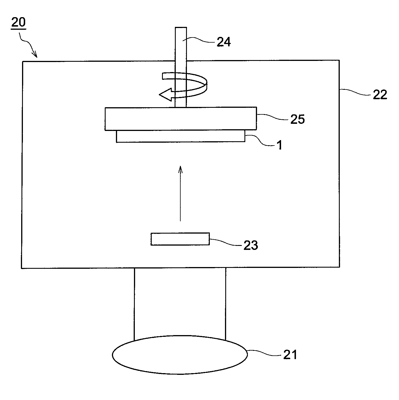
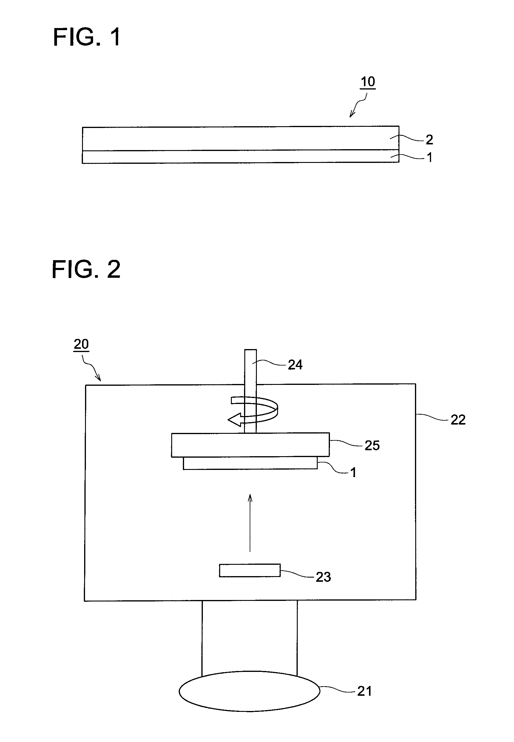
[0046]Using the deposition apparatus 20 shown FIG. 2, the foregoing deposition source materials were deposited on one side of a support (substrate) comprised of a carbon-fiber-reinforced resin sheet to form a phosphor layer.

[0047]First, the deposition source materials were charged into the resistance heating crucible 23, the substrate (1) was set onto the substrate holder 25 which was pivotable by the rotation mechanism 24 and the distance between the substrate 1 and the resistance heating crucible 23 was adjusted to 400 mm. Subsequently, after the inside of the deposition apparatus 22 was evacuated by the vacuum pump 21, Ar gas was introduced thereto and the degree of vacuum was adjusted to 0.1 Pa, then, the temperature of the substrate (1) w...


PUM

PropertyMeasurementUnit
melting pointaaaaaaaaaa
wavelengthaaaaaaaaaa

Abstract

Disclosed is a scintillator plate comprising on a substrate a phosphor layer formed by a process of vapor deposition, wherein a thallium compound having a melting point within ±70° C. of that of CsI and CsI are deposited on a substrate to form a thallium-activated phosphor layer.

Description

[0001]This application claims priority from Japanese Patent Application No. JP2006-207628 filed on Jul. 31, 2006, which is incorporated hereinto by reference.FIELD OF THE INVENTION[0002]The present invention relates to a scintillator plate (hereinafter, also denoted as a radiation image conversion panel) for use in formation of a radiation image of the object.BACKGROUND OF THE INVENTION[0003]There have been broadly employed radiographic images such as X-ray images for diagnosis of the conditions of patients on the wards. Specifically, radiographic images using a intensifying-screen / film system have achieved enhancement of speed and image quality over its long history and are still used on the scene of medical treatment as an imaging system having high reliability and superior cost performance in combination. However, these image data are so-called analog image data, in which free image processing or instant image transfer cannot be realized.[0004]Subsequently, there appeared compute...

Claims


Application Information

Patent Timeline
Patent Type & Authority Applications(United States)
IPC IPC(8): G01T1/20C23C16/00
CPCC23C14/0694
Inventor SAKAI, MIKASHOJI, TAKEHIKO
Owner KONICA MINOLTA MEDICAL & GRAPHICS INC
Why Eureka
Try Eureka