
One-way synchronization of a two-way QKD system

a two-way synchronization and qkd technology, applied in the field of quantum cryptography, can solve problems such as reducing the chance of obtaining false detection

Active Publication Date: 2006-09-07
MAGIQ TECH INC
View PDF2 Cites 9 Cited by
  • Summary
  • Abstract
  • Description
  • Claims
  • Application Information

AI Technical Summary

Benefits of technology

[0009] An aspect of the invention is a method of synchronizing the transmission of quantum signals between first and second QKD stations (ALICE and BOB) in a two-way QKD system by sending the synchronization (“sync”) signals in only one direction between the two stations. The method includes sending the sync signal from ALICE to BOB and phase locking the sync signal at BOB. The method further includes rapidly switching the operation of the QKD system between three different operating states each having a different timing for the quantum signal. For each operating state, the number of detected quantum signals over a given time period is counted. The QKD system is then placed in the operating state having the greatest number of detected quantum signals. This allows for variations in the timing of the QKD system to be compensated for by adjusting just the laser timing rather than the timing of all of the timed elements in the QKD system.
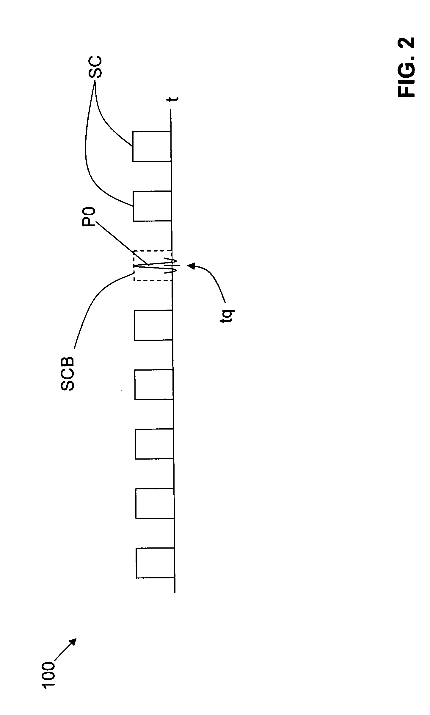
[0010] The method optionally includes adding “blank” sync pulses that overlap the quantum signals returning to BOB from ALICE. This reduces the chance of obtaining a false detection due to scattering from a sync pulse that overlaps the quantum pulse.

Problems solved by technology

This reduces the chance of obtaining a false detection due to scattering from a sync pulse that overlaps the quantum pulse.

Method used


Image

  • One-way synchronization of a two-way QKD system
  • One-way synchronization of a two-way QKD system
  • One-way synchronization of a two-way QKD system

Examples


Embodiment Construction

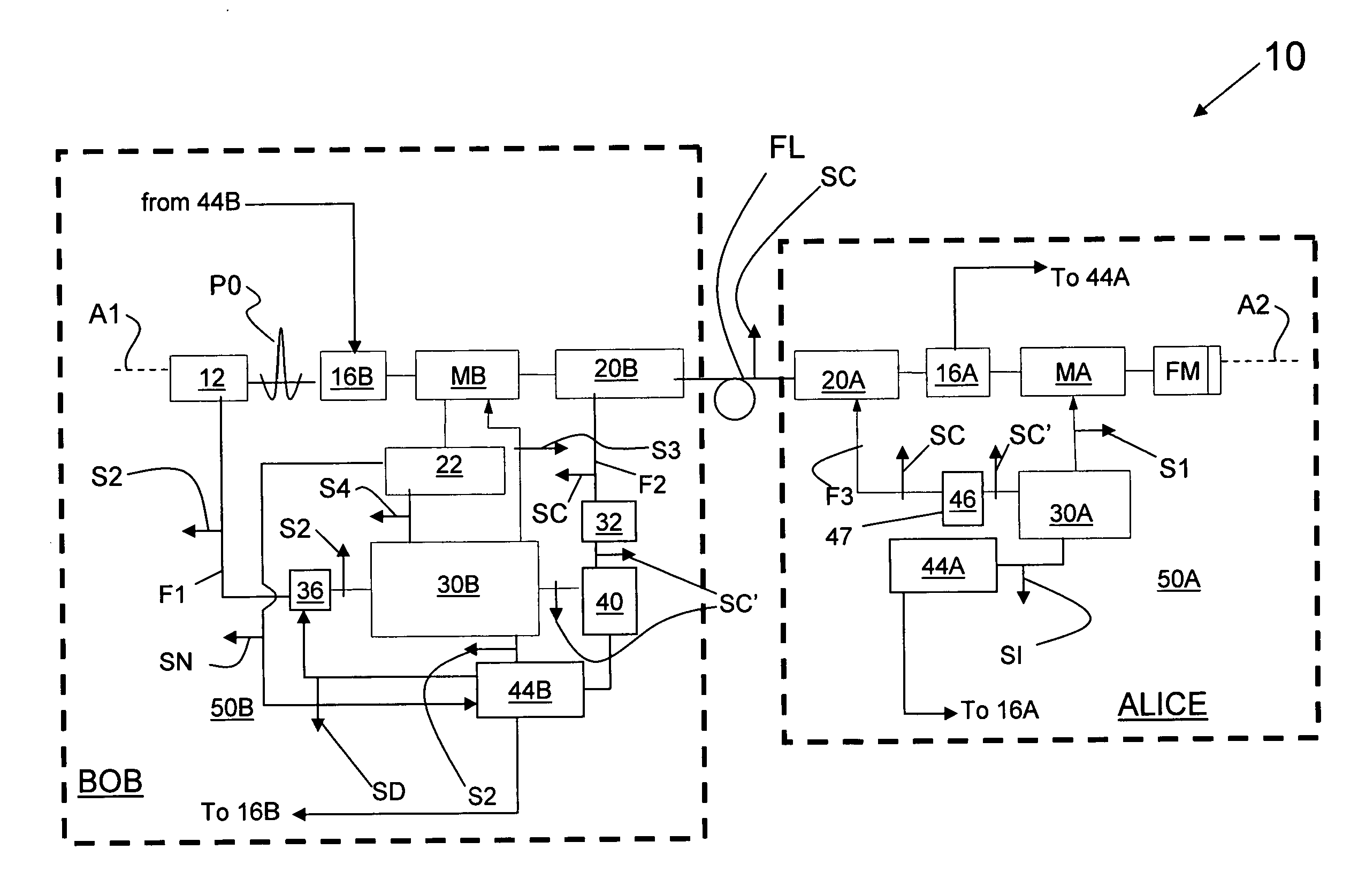
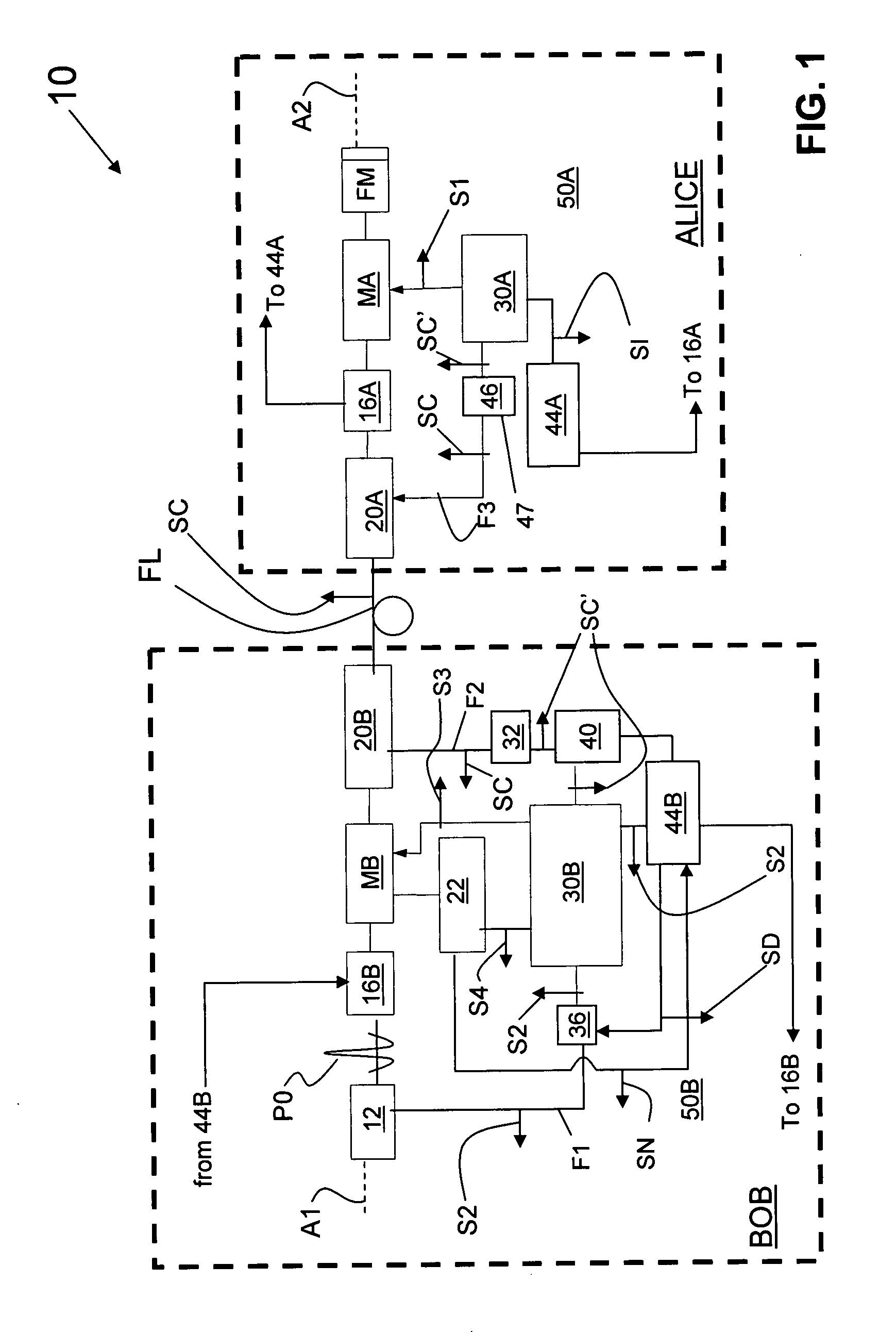
[0015]FIG. 1 is a schematic diagram of a two-way QKD system 10 having two QKD stations BOB and ALICE optically coupled to one another by an optical fiber link FL of length L. The construction of the two QKD stations BOB and ALICE is described below, followed by the method of operation that allows for one-way synchronization of the two QKD stations.

BOB

[0016] With continuing reference to FIG. 1, BOB includes, in order along an optical axis A1, a quantum laser 12, a variable optical attenuator (VOA) 16B, a phase modulator unit MB, and an optical modem 20B. The term “quantum laser” is used herein to emphasize the fact that quantum laser 12 generates optical pulses P0 that serve as the quantum signals (pulses) for system 10.

[0017] Phase modulator unit MB includes a random number generator (RNG), a phase modulator and a phase modulator driver, which are not individually shown for ease of illustration. Phase modulator unit MB is adapted to impart a phase to a quantum signal passing the...


PUM


Abstract

A method of synchronizing the operation of a two-way QKD system by sending a sync signal (SC) in only one direction, namely from one QKD station (ALICE) to the other QKD station (BOB). The one-way transmission greatly reduces the amount of light scattering as compared to two-way sync signal transmission. The method includes phase-locking the sync signal at BOB and dithering the timing of the quantum signals so as to operate the QKD system in three different operating states. The number of detected quantum signals is counted for each state for a given number of detector gating signals. The QKD system is then operated in the state associated with the greatest number of detected quantum signals. This method is rapidly repeated during the operation of the QKD system to compensate for timing errors to maintain the system at or near its optimum operating state. The method allows for only having to adjust the timing of a single timed element—namely, the quantum laser—to compensate for timing variations, rather than having to adjust the timing of all or some of the timed elements in the QKD system.

Description

CROSS-REFERENCE TO RELATED APPLICATIONS [0001] The present patent application is related to PCT patent application no. PCT / US2004 / 03299, entitled “QKD systems with robust timing,” published on Aug. 26th, 2004 as WO 2004 / 073234 A2, and to PCT patent application no. PCT / US2004 / 02429, entitled “Detector autocalibration in QKD systems,” which patent applications are incorporated by reference herein.FIELD OF THE INVENTION [0002] The present invention relates to quantum cryptography, and in particular relates to synchronizing the operation of the two quantum key distribution (QKD) stations in a two-way QKD system. BACKGROUND OF THE INVENTION [0003] Quantum key distribution involves establishing a key between a sender (“ALICE”) and a receiver (“BOB”) by using weak (e.g., 0.1 photon on average) optical signals (“quantum signals”) transmitted over a “quantum channel.” The security of the key distribution is based on the quantum mechanical principle that any measurement of a quantum system in...

Claims


Application Information

Patent Timeline
IPC IPC(8): H04K1/00
CPCH04L9/12H04L9/0852
Inventor YOUNG, JONATHANLAGASSE, MICHAEL J.
Owner MAGIQ TECH INC
Learn More