Apparatus and method for sensor deployment and fixation

a technology for fixing devices and sensors, applied in medical science, diagnostics, angiography, etc., can solve problems such as difficult environment in which to reliably secure sensors or other apparatuses, difficulty in detecting and detecting abnormalities, and difficulty in detecting abnormalities,

Active Publication Date: 2006-09-07
ST JUDE MEDICAL LUXEMBOURG HLDG II S A R L SJM LUX II
View PDF99 Cites 33 Cited by
  • Summary
  • Abstract
  • Description
  • Claims
  • Application Information

AI Technical Summary

Problems solved by technology

As this concept has seen continued research and development, issues regarding intracorporeal fixation of the sensor have come to light.
This is a difficult environment in which to secure a sensor or other apparatus reliably without unduly restricting blood flow or impairing the vessel wall.
The pulmonary artery is a particularly challenging location in which to secure an intracorporeal device because, in addition to the above considerations, the vessel is especially thin, compliant and prone to perforation.
These attempts fall short of meeting all of the necessary requirements outlined above.
This primary requirement leads to a mismatch in compliance, with that of the stent dominating.
Because undiseased vessels are usually more compliant compared to diseased ones, this compliance mismatch is amplified when placing a stent in healthy vasculature.
Accurate stent sizing to prevent migration and to avoid perforation of the vessel wall could be more difficult in healthy vasculature, especially the pulmonary artery, which has a smooth inner lining and greater compliance than most vessels.
This determination presents its own set of challenges and requires an unnecessary increase in complexity, e.g., in deployment, and risk of complication.
Therefore, the use of a stent to maintain an intracorporeal device in a vessel is not optimal.

Method used


Image

  • Apparatus and method for sensor deployment and fixation
  • Apparatus and method for sensor deployment and fixation
  • Apparatus and method for sensor deployment and fixation

Examples


Embodiment Construction

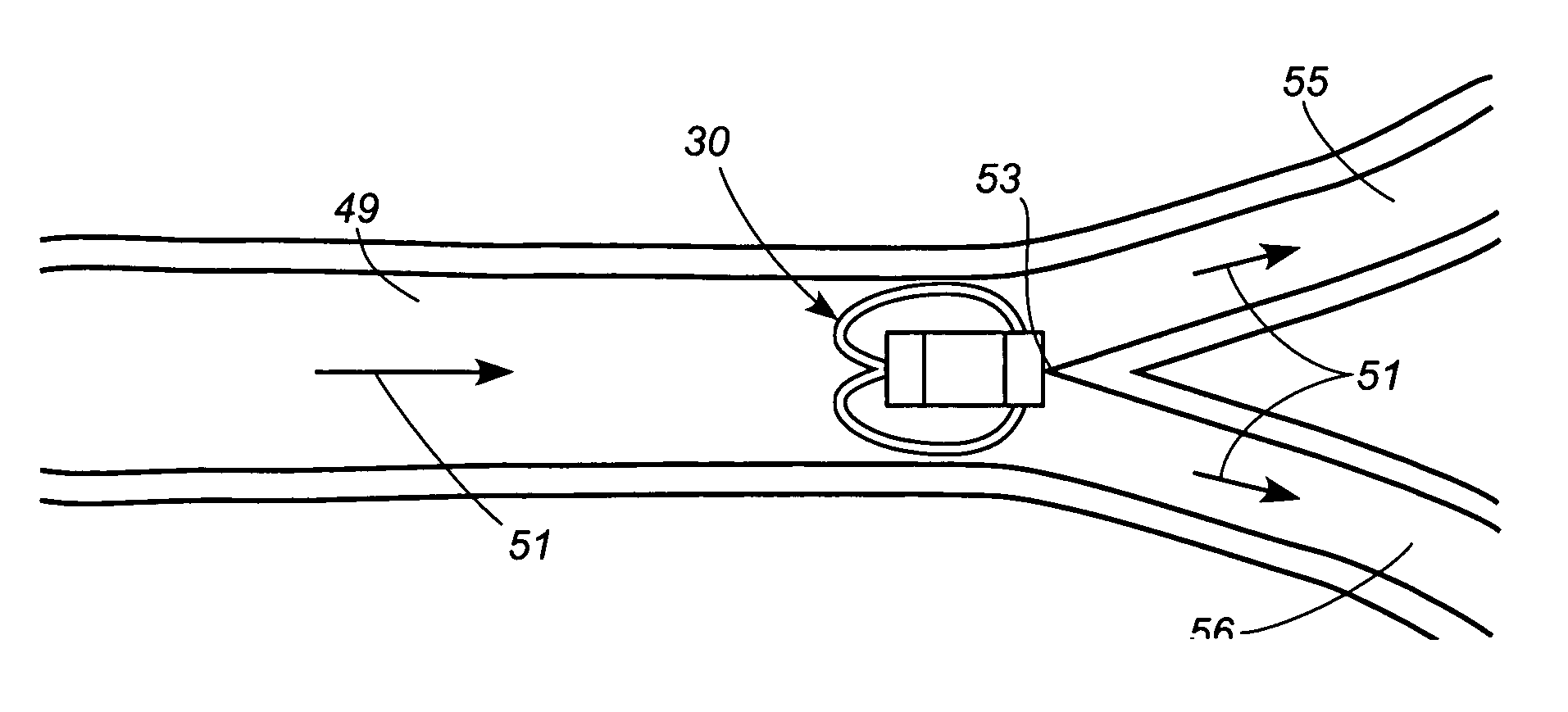
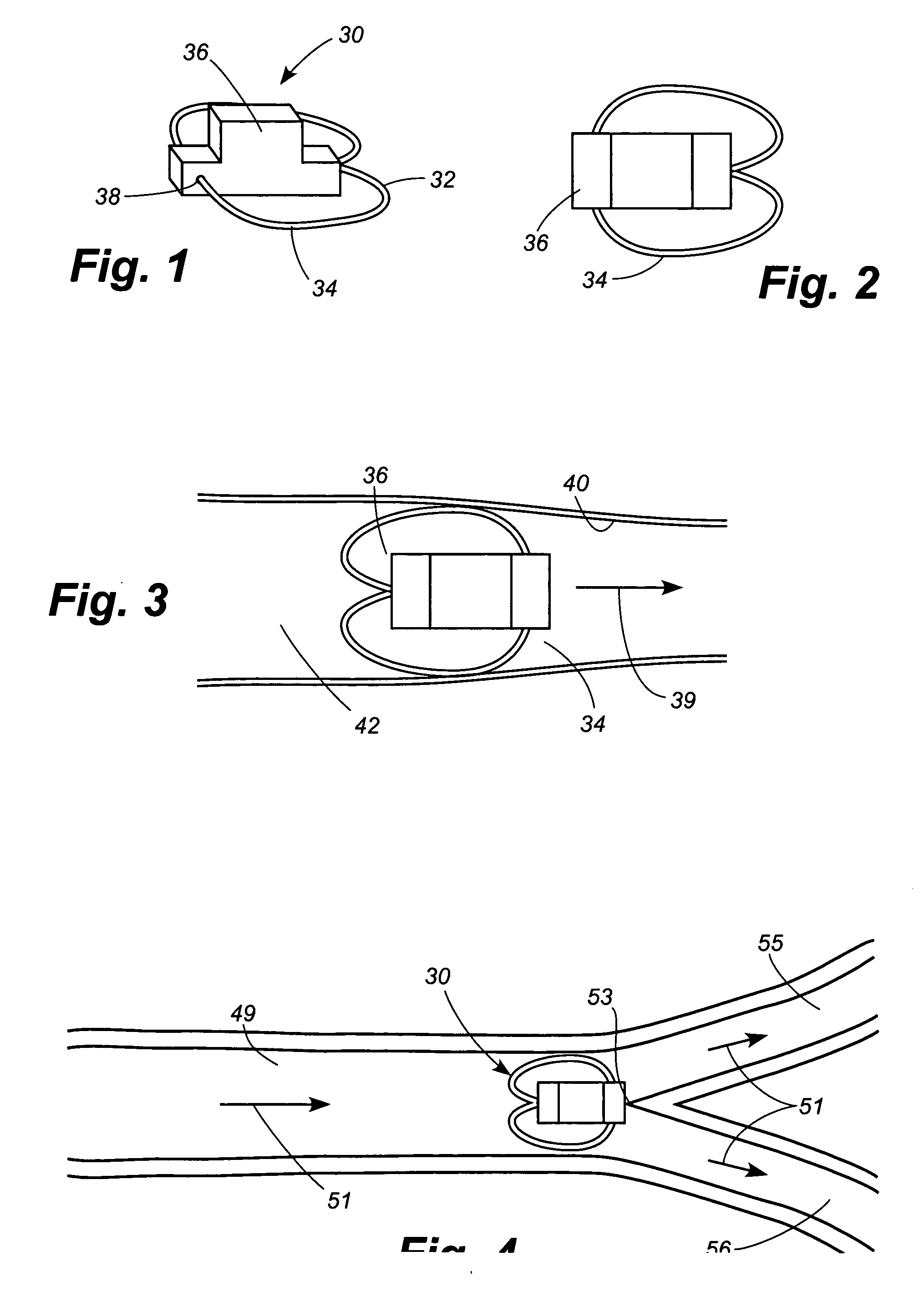
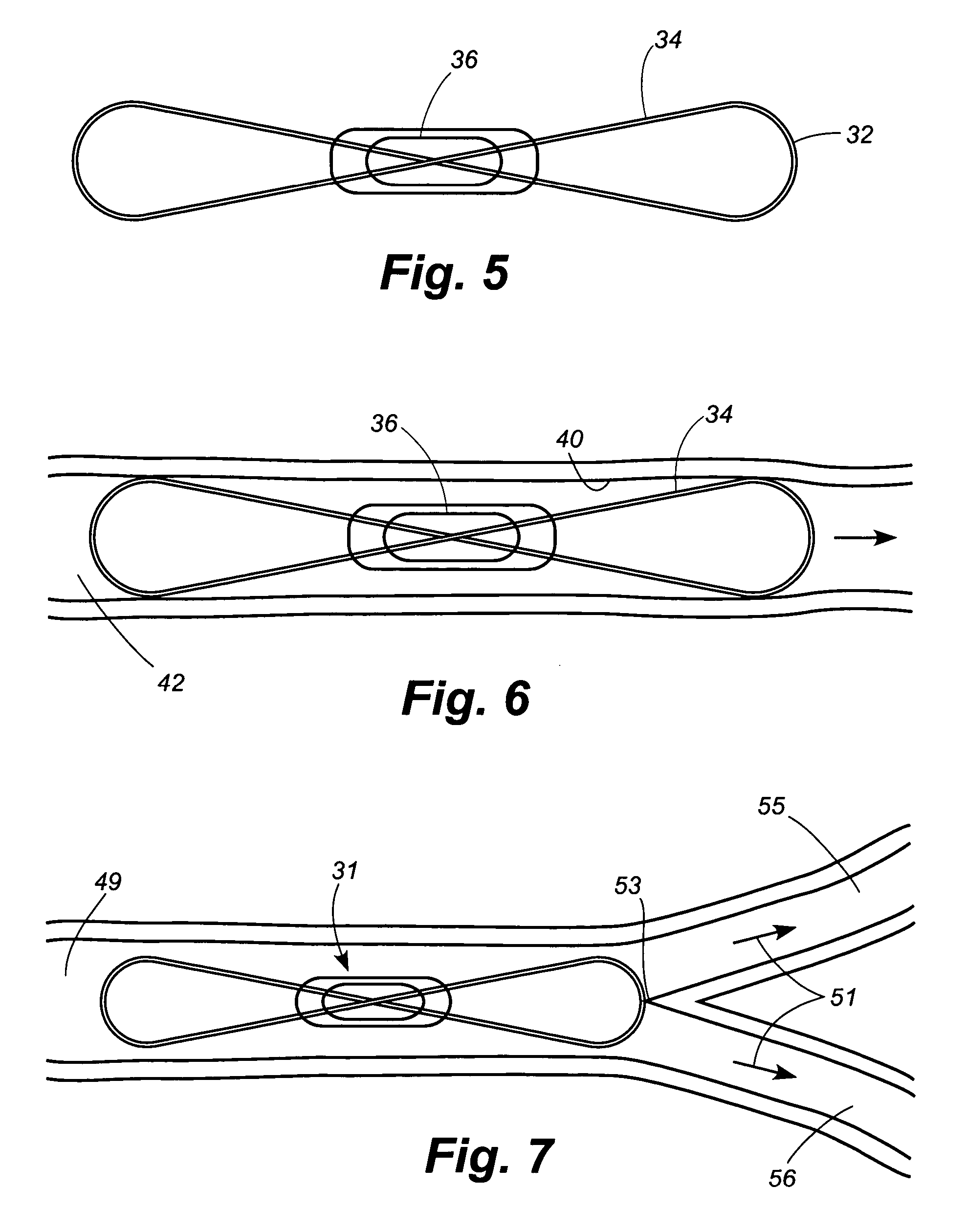
[0046] An implant assembly of this invention includes an intracorporeal device and an anchoring structure used to stabilize the intracorporeal device in the body, such as in a vessel. Delivery systems of this invention are used to deploy and secure the implant assembly in a desired location in a vessel and include a delivery apparatus and an implant assembly. The intracorporeal device may be a pressure sensor, further described below. The anchoring structure may be a structure capable of being introduced into the body via a delivery apparatus, such as a catheter, and then lodging within the vessel. Anchoring structures of this invention may include structure including opposed wire loops, radial wire array structures, and daisy petal structures, all further described below.

[0047] All of the implant assemblies of this invention obstruct approximately 50% or less of the cross-sectional area of the vessel in which it resides. Preferably, the implant assemblies obstruct 20% or less of t...


PUM


Abstract

An implant assembly is implanted in vivo within a vascular system in which a vessel divides at a furcation into two sub-vessels, each sub-vessel having a diameter smaller than the diameter of said vessel. An implant assembly is released into a vessel such as a pulmonary arterial vessel of a patient. The implant assembly has a diameter smaller than or substantially equal to the inner diameter of the vessel and larger than the inner diameter of each of the sub-vessels. The implant assembly is configured so that it moves downstream within the vessel along with the flow of blood. When the implant assembly reaches a furcation where the vessel divides, the implant assembly is too large and not sufficiently compliant to fit through either of the smaller branch vessels. The implant assembly thus lodges at the furcation, prevented from moving downstream by being too large and stiff to fit into the branch vessels, and prevented from moving upstream by the flow of blood through the arteries. Alternatively, the implant assembly has a diameter greater than a vessel and compliance characteristics such that, upon release, the implant assembly travels down a narrowing vessel until an interference fit is created between the anchor structure and the vessel wall, thereby preventing further distal movement.

Description

RELATED APPLICATION DATA [0001] This application claims priority to provisional U.S. Application No. 60 / 658,358, filed Mar. 3, 2005, to provisional U.S. Application No. 60 / 662,210, filed Mar. 14, 2005, and to non-provisional U.S. application Ser. No. 11 / 180,840, filed Jul. 13, 2005, currently pending.FIELD OF THE INVENTION [0002] This invention relates generally to implantation of intracorporeal devices into vessels, and to fixing the devices, either permanently or temporarily, within the vessel. BACKGROUND OF THE INVENTION [0003] In recent years, the long-sought goal of implantable biosensors has begun to see realization and, in some cases, clinical use. As this concept has seen continued research and development, issues regarding intracorporeal fixation of the sensor have come to light. Particularly within blood vessels, the sensor is subjected to a continuous, pulsatile flow. This is a difficult environment in which to secure a sensor or other apparatus reliably without unduly re...

Claims


Application Information

Patent Timeline
Patent Type & Authority Applications(United States)
IPC IPC(8): A61B5/02
CPCA61B5/0031A61B5/0215A61B5/03A61B5/076A61B5/6882A61F2/848A61F2002/9522A61F2250/0002A61F2/82A61F2/95A61F2002/9511A61F2/9522
Inventor WHITE, JASONTUMLIN, KELLY
Owner ST JUDE MEDICAL LUXEMBOURG HLDG II S A R L SJM LUX II
Why Eureka
Try Eureka