Covering for an endoprosthetic device and methods of using for aneurysm treatment

a technology of endoprosthetic devices and endoprosthetic devices, which is applied in the field of endoprosthetic devices, can solve the problems of inaccessible open procedures for intracranial aneurysms, surgical procedures carry a significant degree of morbidity and mortality, and the rupture of aneurysms may be fatal, so as to reduce the risk of aneurysm rupture, reduce the speed and amount of blood flow, and reduce the risk of aneurysms

Inactive Publication Date: 2006-09-07
MEDINOL LTD
View PDF19 Cites 28 Cited by
  • Summary
  • Abstract
  • Description
  • Claims
  • Application Information

AI Technical Summary

Benefits of technology

[0014] Methods of using the endoprosthetic device of the invention, e.g., to treat aneurysms, are also encompassed by the present invention. In such methods, the covered endoprosthetic device is placed in the lumen of the blood vessel or artery in the area of the aneurysm and is positioned such that the central portion of the sheath is facing the aneurysm. Thus, blood flow is reduced in the aneurysm. The reduced speed and amount of blood flow to the aneurysm may trigger a thrombosis which further excludes the aneurysm from blood pressure. This reduces the risk of aneurysm rupture.
[0015] Any aneurysm can be treated according to the methods of the invention. In one embodiment, the aneurysm is an intracranial aneurysm. More particularly, the intracranial aneurysm may be in proximity to one or mor...

Problems solved by technology

Depending upon where in the body the aneurysm is located, a ruptured aneurysm may be fatal.
These open surgical procedures carry a significant degree of morbidity and mortality.
Further, some intracranial aneurysms are inaccessible to open procedures due to their locations deep inside the brain tissue.
The many shortcomings of this approach include the unpredictable nature of the procedure (thus leaving a nu...

Method used


Image

  • Covering for an endoprosthetic device and methods of using for aneurysm treatment
  • Covering for an endoprosthetic device and methods of using for aneurysm treatment
  • Covering for an endoprosthetic device and methods of using for aneurysm treatment

Examples


Embodiment Construction

[0027] The following detailed description should be read with reference to the drawings in which like elements in different drawings are numbered identically. The drawings, which are not necessarily to scale, depict selected embodiments and are not intended to limit the scope of the invention.

[0028] Examples of constructions, materials, dimensions, and manufacturing processes are provided for selected elements. All other elements employ that which is known to those skilled in the field of the invention. Those skilled in the art will recognize that many of the examples provided have suitable alternatives that may also be used.

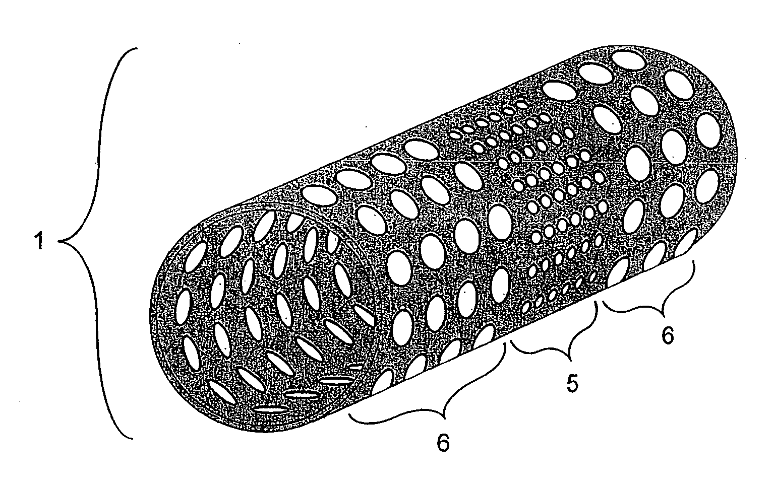
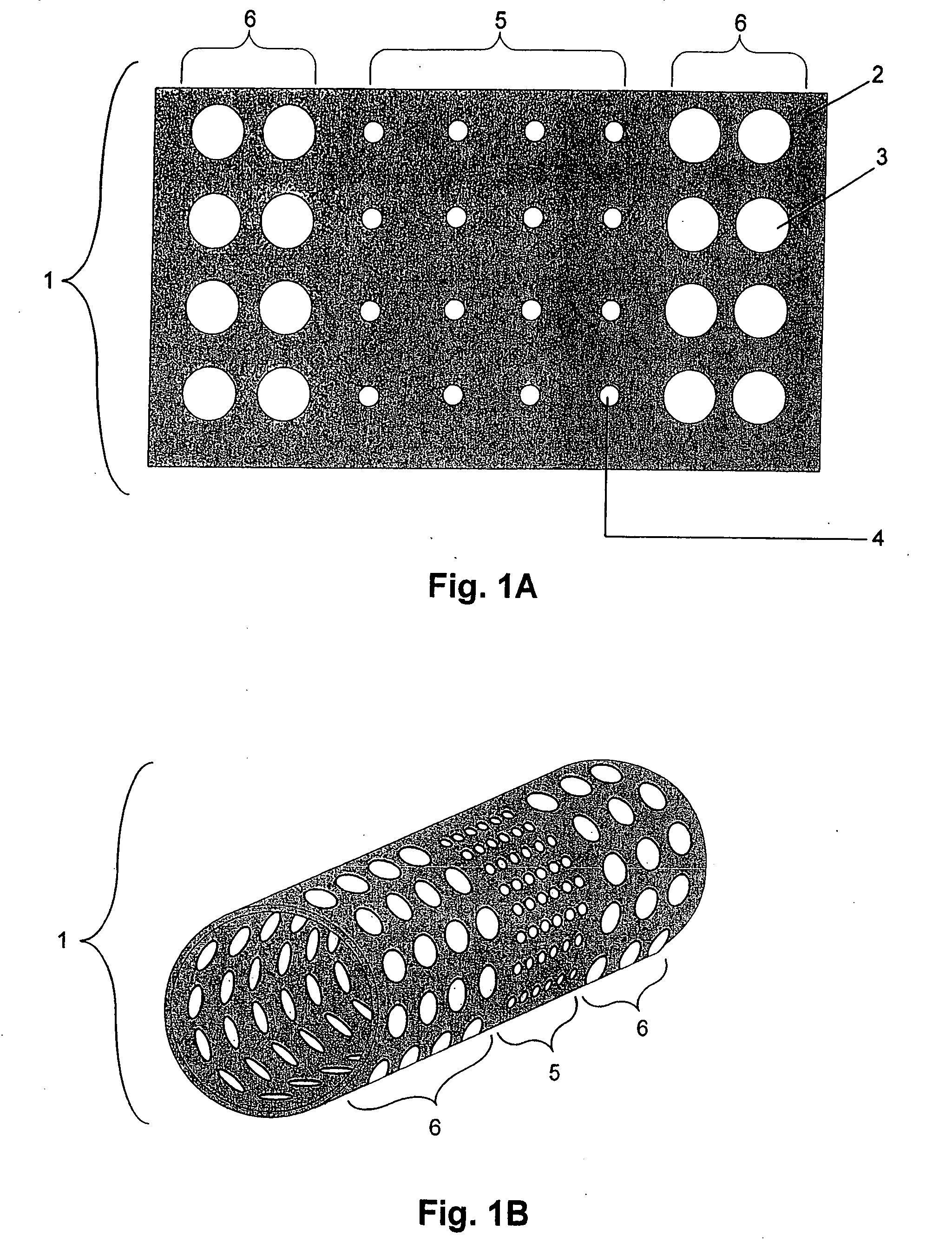
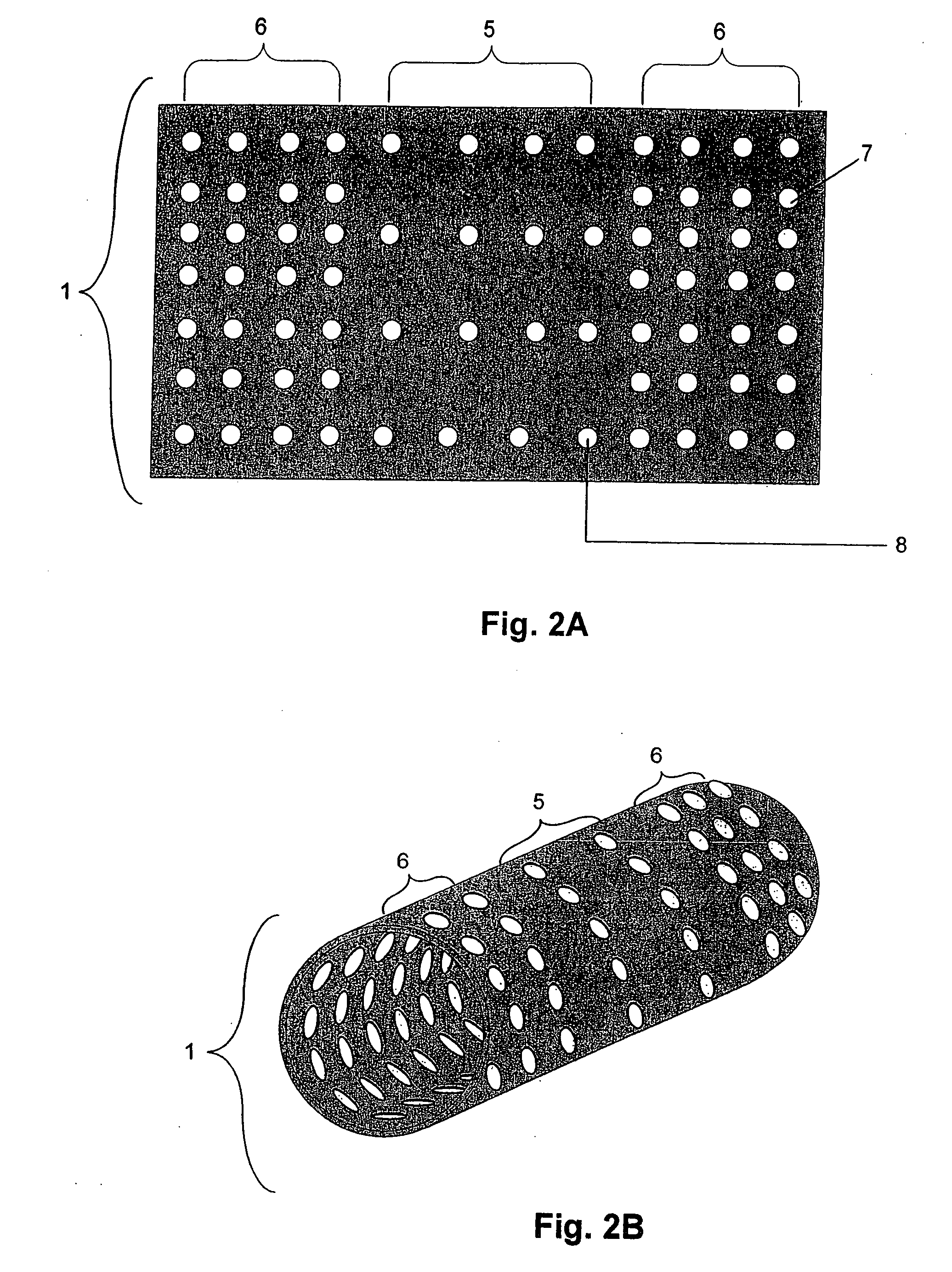
[0029] The covered endoprosthetic devices of the invention are covered with a sheath. The sheath preferentially restricts or causes a restriction of blood flow to the aneurysm while leaving blood flow to surrounding areas (e.g., small perforator vessels or arteries around the neck of the aneurysm) substantially unaffected. In one embodiment, blood flow to the ...


PUM


Abstract

The present invention relates to covered endoprosthetic devices. Covered endoprosthetic devices comprise an endoprosthesis and a sheath. The sheath comprises a central portion and outer portions, wherein the central portion preferentially restricts or causes a restriction of blood flow. Blood flow can be reduced by the central portion of the sheath by varying the permeability of the sheath or by having projections on the sheath that slow blood flow. Permeability may be provided by perforations or holes in the material of the sheath or by varying the polymer structure that makes up the sheath itself. The outer portions of the sheath do not substantially reduce blood flow. Methods of using sheath-covered endoprosthetic devices of the invention to treat aneurysms, especially aneurysms in proximity to small perforator vessels or arteries, are also encompassed.

Description

[0001] This application is a continuation-in-part application of U.S. patent application Ser. No. 10 / 952,360, filed Sep. 27, 2004 and also claims the benefit of priority of U.S. Provisional Application No. 60 / 673,304, filed Apr. 19, 2005, both of which are incorporated herein by reference in their entirety.FIELD OF THE INVENTION [0002] The present invention relates to a covering for endoprosthetic devices. Methods of using endoprosthetic devices covered by a sheath of the invention to treat aneurysms are also encompassed. The coverings preferentially restrict blood flow to the aneurysm while leaving surrounding areas substantially unaffected. In specific embodiments, aneurysms in proximity to small perforator vessels or arteries are treated using devices and methods of the invention. BACKGROUND OF THE INVENTION [0003] An aneurysm is a phenomenon in which the wall of a blood vessel, typically an artery, is abnormally dilated due to weakening of the vessel wall and a bulb or ball shap...

Claims


Application Information

Patent Timeline
IPC IPC(8): A61F2/06A61F2/82
CPCA61B5/0215A61B5/6882A61F2/07A61F2/90A61F2002/823A61F2250/0023A61F2002/075A61F2/06
Inventor RICHTER, JACOB
Owner MEDINOL LTD
Why Eureka
Try Eureka