Force compensated comb drive

a comb drive and force compensation technology, applied in the direction of acceleration measurement using interia forces, devices using electric/magnetic means, instruments, etc., can solve the problems of thermal propagation errors, change in the amplitude of the proof mass driving force, and incompatibility of the size of the chamber and the complexity of the control with the miniaturization afforded by the mems device, etc., to achieve the effect of improving the accuracy of tuning fork gyroscop

Active Publication Date: 2006-09-14
CHARLES STARK DRAPER LABORATORY
View PDF4 Cites 24 Cited by
  • Summary
  • Abstract
  • Description
  • Claims
  • Application Information

AI Technical Summary

Benefits of technology

[0006] It is a further object of this invention to provide such an improved force compensated comb device for a MEMS which eliminates thermal propagation errors associated with temperature sensors used to correct for temperature induced force variations.
[0007] It is a further object of this invention to provide such an improved force compensated comb device for a MEMS which corrects for temperature/pressu...

Problems solved by technology

In all of these applications any changes in the force applied by the comb device can produce errors in the output signal.
In particular, in a MEMS gyroscope, the change in temperature or pressure results in a change in the amplitude of the proof mass driving force which will appear erroneously as a change in input gyroscope rate or sensitivity.
But the size of the chamber and complexity of...

Method used


Image

  • Force compensated comb drive
  • Force compensated comb drive
  • Force compensated comb drive

Examples


Embodiment Construction

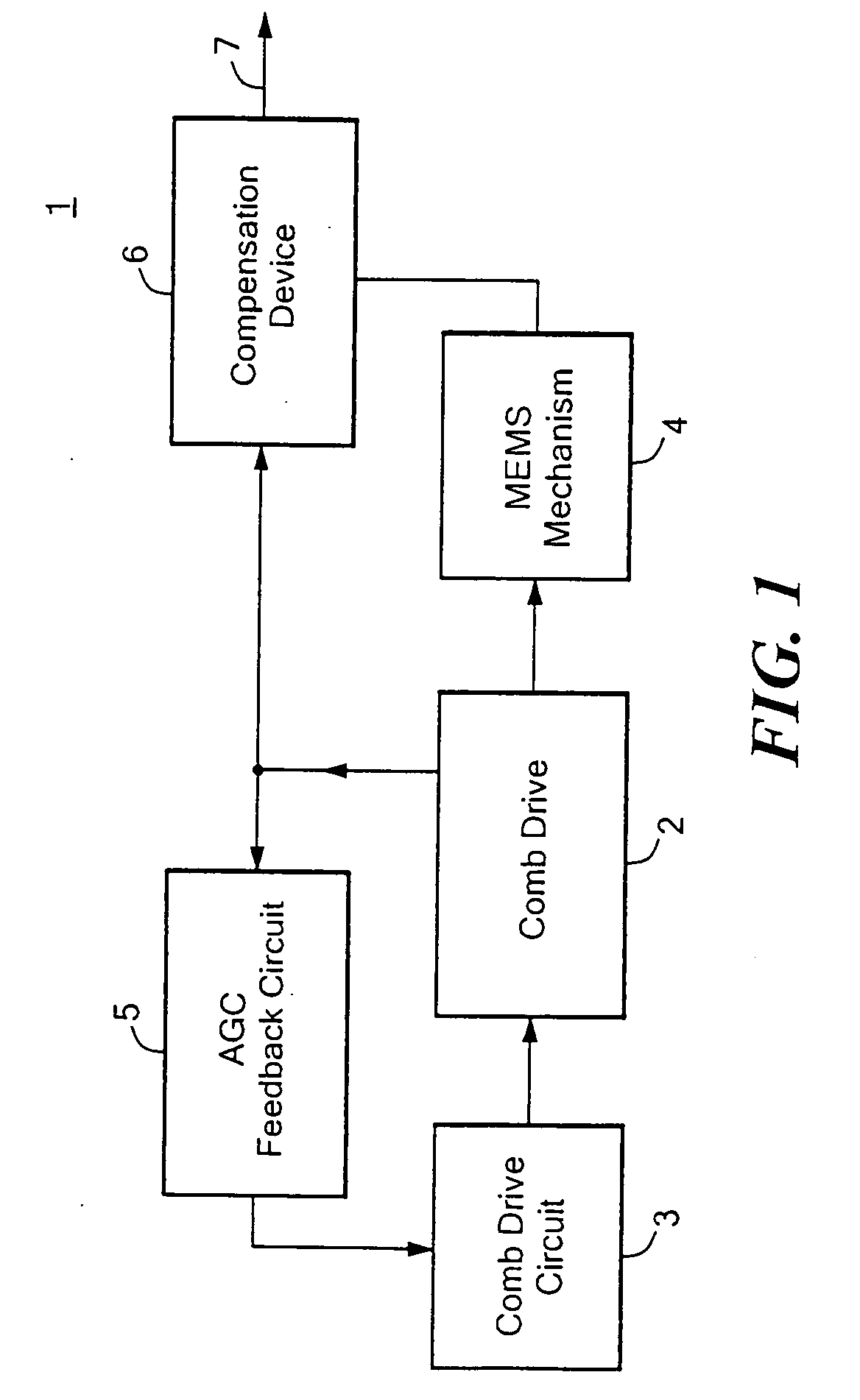
[0023] There is shown in FIG. 1 a force compensated comb drive for a microelectromechanical system 1, typically but not necessarily fixed volume, according to this invention. Comb drive 2 is driven by comb drive circuit 3 to operate (e.g., vibrate) a MEMS mechanism 4. Any change in the motion of comb drive 2 is sensed and generates an automatic gain control (AGC) signal in the automatic gain control feedback circuit 5 which is fed back to the comb drive circuit 3 to reestablish the original proof mass displacement amplitude. The AGC signal is applied to the motor combs so that the comb force is adjusted to maintain the motion amplitude at a constant value.

[0024] One typical MEMS mechanism 4 is in a closed package having a fixed volume. Therefore, as will be explained more fully hereinafter, any change in pressure or change in temperature change the force being applied by comb drive 2. Because of silicon material properties and because the dependence of gas viscosity on temperature,...


PUM


Abstract

A force compensated comb drive for a microelectromechanical system includes a MEMS mechanism for providing an output signal representative of a physical quantity; a comb drive for actuating the MEMS mechanism; a comb drive circuit for providing a drive signal to the comb drive for developing a predetermined displacement applied by the comb drive to the MEMS mechanism; an automatic gain control responsive to a change in the force to provide a correction signal to the comb drive circuit to maintain the predetermined motion; and a compensation device responsive to the correction signal for adjusting the output signal of the MEMS mechanism to compensate for errors in the output signal due to a change in the predetermined force.

Description

FIELD OF INVENTION [0001] This invention relates to a force compensated comb drive for a fixed volume microelectromechanical system (MEMS). BACKGROUND OF INVENTION [0002] Comb drives are used in a number of microelectromechanical systems (MEMS) to excite e.g., pressure sensors, optical devices and gyroscopes. In all of these applications any changes in the force applied by the comb device can produce errors in the output signal. For example, in MEMS gyroscopes, the proof mass and comb drive are typically encapsulated in a sealed package with fixed volume at low pressure. Any change in pressure changes in the mean free path and, hence, the force exerted by the comb drive and changes in temperature in the fixed volume result in changes in the pressure and gas viscosity which then effect the force exerted by the comb drive. For a fixed number of molecules in an evacuated fixed volume, the damping force from gas effects and, hence, drive amplitude, is independent of pressure. At near at...

Claims


Application Information

Patent Timeline
IPC IPC(8): G01P15/08
CPCG01C19/5719G01P15/125H02N1/008
Inventor KOUREPENIS, ANTHONY S.WEINBERG, MARC S.ELLIOTT, RICHARDDALEY, STEVEN
Owner CHARLES STARK DRAPER LABORATORY
Why Eureka
Try Eureka