System and method to automatically focus an image reader

Active Publication Date: 2006-09-14
HAND HELD PRODS
View PDF98 Cites 207 Cited by
  • Summary
  • Abstract
  • Description
  • Claims
  • Application Information

AI Technical Summary

Benefits of technology

[0019] In another aspect, the invention features an image reader for minimizing ambient light image degradation. The image reader comprises an integrated circuit including at least an image sensor array, the image sensor array providing a signal suitable for light intensity determination. The image reader also comprises a rolling shutter control module configured to sequentially expose a plurality line of pixels in the image sensor array. The image reader further comprises a global electronic shutter control module configured to simultaneously expose the plurality of lines of pixels in the image sensor array, wherein one of the rolling shutter control module and the global electronic shutter control module is capable of being selected to control the image sensor array in response to the signal suitable for light intensity determination. In one embodiment of the image reader, the signal suitable for light intensity determination includes information related to an intensity of a light source of the image reader. In another embodiment of the image reader, the signal suitable for light intensity determination is useful for determining whether a minimum integration time is satisfied. In a further embodiment of the image reader, the signal suitable for light intensity determination is useful for determining whether the exposure time (also known as the integration time) for the current environmental condition is less

Problems solved by technology

In operation, the rolling shutter architecture suffers from at least two disadvantages: image distortion and image blur.
The effect of image distortion is most pronounced when fast moving objects are visually recorded.
Due to batte

Method used


Image

  • System and method to automatically focus an image reader
  • System and method to automatically focus an image reader
  • System and method to automatically focus an image reader

Examples


Embodiment Construction

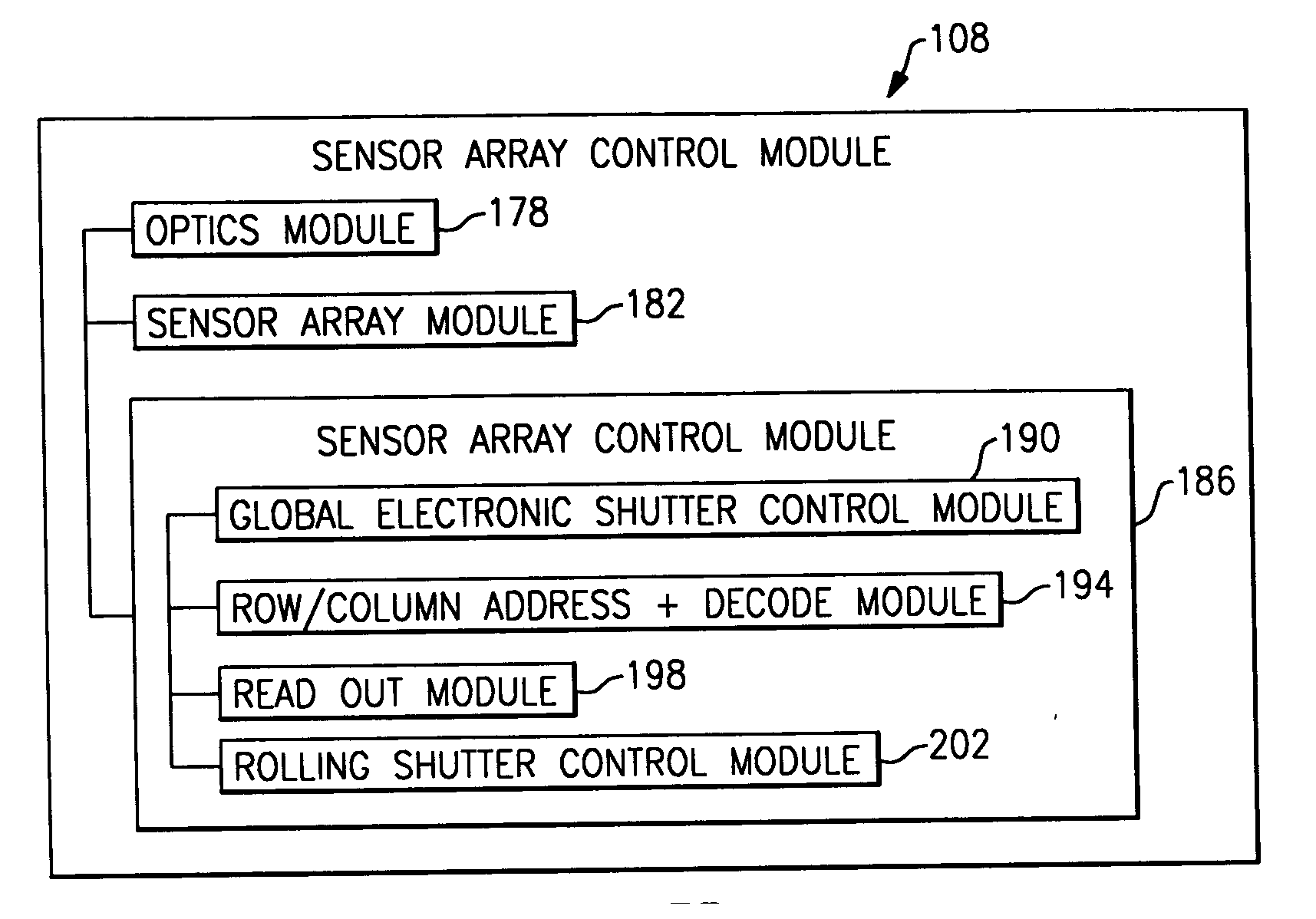
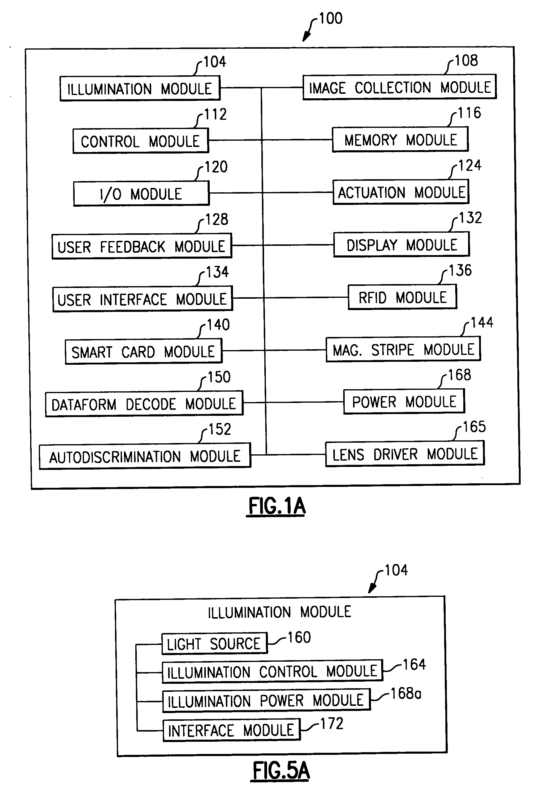
[0061] The invention features an image reader and a corresponding method for capturing a sharp non-distorted image of a target. In one embodiment, the image reader comprises a two-dimensional CMOS based image sensor array, a timing module, an illumination module, and a control module all in electrical communication with each other. The illumination module shines light on the target, such as a symbology such as one or two-dimensional bar code, so that reflected light that can be collected and processed by the image sensor array. The time during which the target is illuminated is referred to as the illumination period. The capture of the image by the image sensor array is driven by the timing module that, in one embodiment, is able to simultaneously expose all or substantially all of the pixels in the array. The simultaneous exposure of the pixels in the sensor array enables the image reader to capture a distortion free image. The time during which the pixels are collectively activate...


PUM


Abstract

The invention features a system and method to automatically focus an image reader using a single frame of image data. The method comprises exposing sequentially a plurality of rows of pixels in the image sensor. The method further comprising varying in incremental steps the focus of the image reader's optical system from a first setting where a distinct image of objects located at a first distance from the image reader is formed on the image sensor to a second setting where a distinct image of objects located at a second distance from the image reader is formed on the image sensor. As part of the method, the varying of the focus of the optical system occurs during the exposure of the plurality of rows of pixels.

Description

CROSS-REFERENCE TO RELATED APPLICATIONS [0001] This application is related to the application enumerated below, filed with the United States Patent and Trademark Office contemporaneously with the present application on Mar. 11, 2005 by Express Mail and subject to assignment to the same assignee of this application, the disclosure of which is incorporated herein by reference in its entirety: U.S. patent application Ser. No. ______, Attorney Docket Number 283-458.11, entitled “Bar Code Reading Device With Global Electronic Shutter Control.”FIELD OF THE INVENTION [0002] The invention relates to image data collection in general and particularly to an image data collector with coordinated illumination and global shutter control. BACKGROUND OF THE INVENTION [0003] Many traditional imager readers, such as hand held and fixed mounted bar code and machine code readers, employ charge-coupled device (CCDs) based image sensors. A CCD based image sensor contains an array of electrically coupled ...

Claims


Application Information

Patent Timeline
IPC IPC(8): G06K7/10
CPCG06K7/10732G06K7/10831G06K7/10811H04N23/689G06K7/10722
Inventor WANG, YNJIUNHAVENS, WILLIAM H.
Owner HAND HELD PRODS
Why Eureka
Try Eureka