Inductive output tube tuning arrangement

a technology of inductive output tube and tuning arrangement, which is applied in the direction of discharge tube/lamp details, discharge tube luminescnet screens, electric discharge lamps, etc., can solve the problem of density modulation of electron beams, and achieve the effect of minimising effects

Inactive Publication Date: 2006-09-14
E2V TECH (UK) LTD
View PDF4 Cites 3 Cited by
  • Summary
  • Abstract
  • Description
  • Claims
  • Application Information

AI Technical Summary

Benefits of technology

[0009] The use of a capacitative tuning element in an integral output cavity of an IOT allows the IOT to have a fixed output cavity geometry, rather than a tunable cavity door as embodied in external cavity ...

Problems solved by technology

This causes density mod...

Method used


Image

  • Inductive output tube tuning arrangement
  • Inductive output tube tuning arrangement
  • Inductive output tube tuning arrangement

Examples


Embodiment Construction

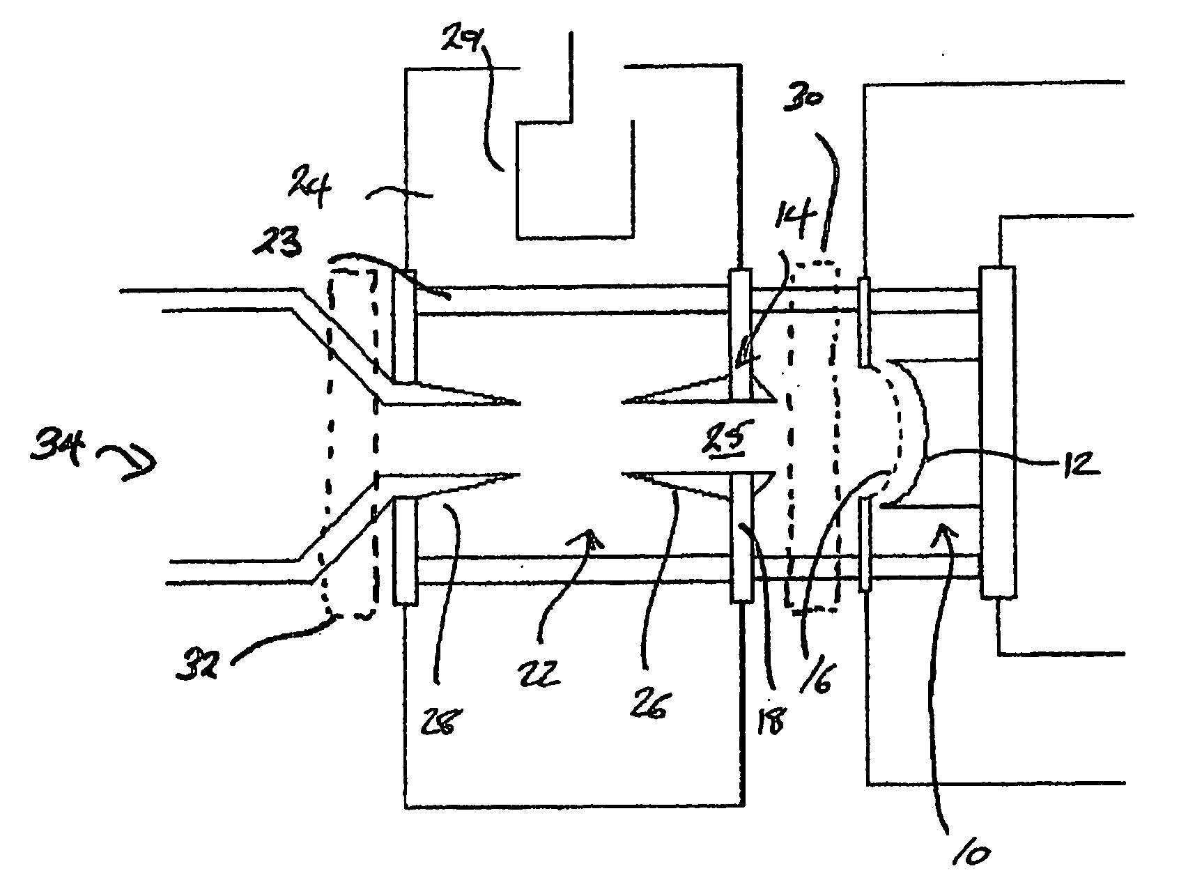
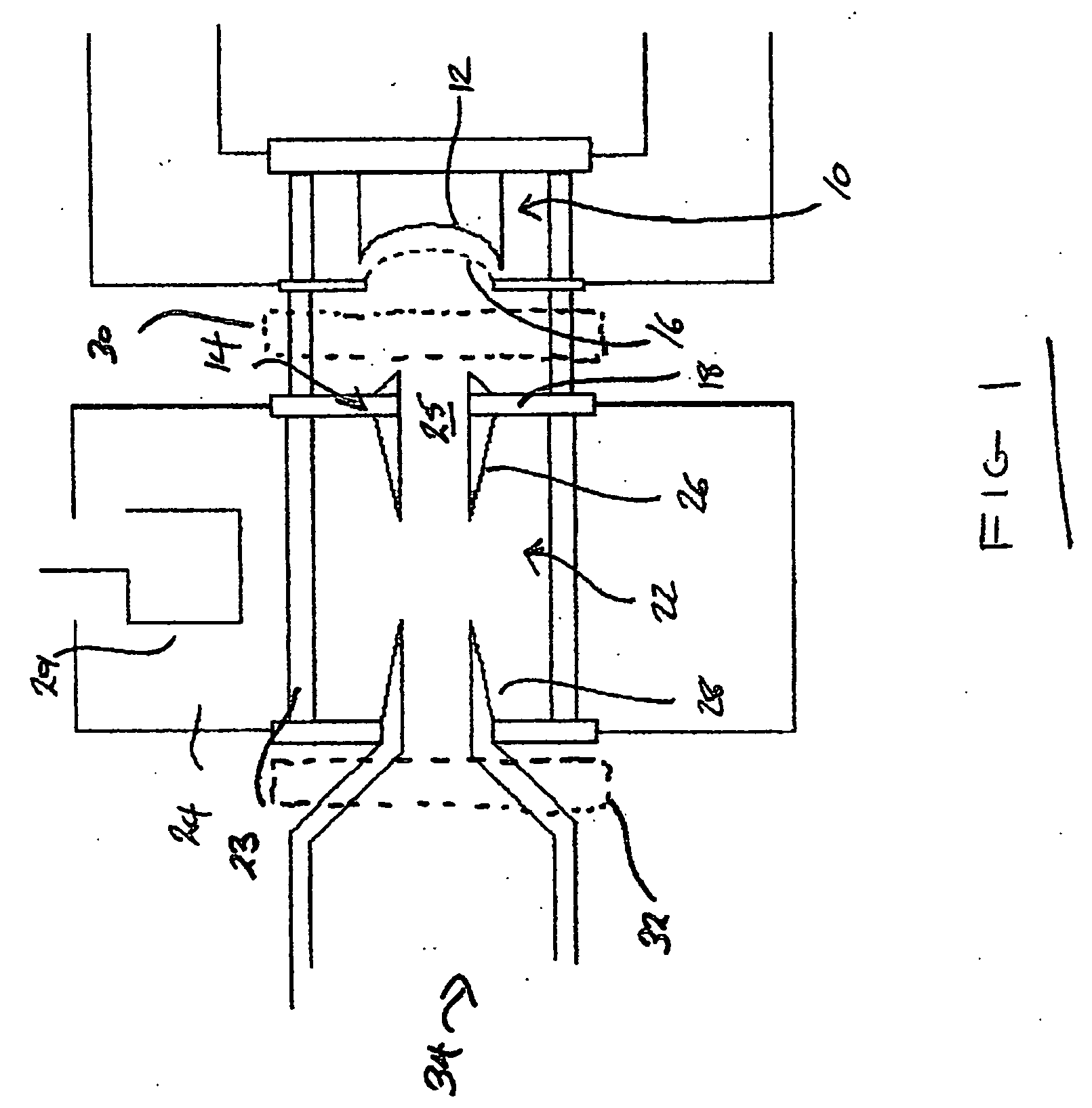
[0018] The embodiment of the invention is an integral output cavity Inductive Output Tube (IOT). It is important to note that the invention is applicable to such IOTs because an integral cavity IOT is capable of better performance for continuous wave applications such as scientific devices but tunability is not usually required. We appreciated, though, that some tunability for fine tuning such an IOT is useful so as to optimise a particular IOT to the application.

[0019] A known external cavity IOT is first described, shown in FIG. 1, which comprises an electron gun 10 for generating an electron beam. The electron beam is created from a heated cathode 12 held at a negative beam potential of around −36 kV and accelerated towards and through an aperture in a grounded anode 14 formed as part of a first portion of a drift tube, (or interaction region), 22 described later. In normal use, the electron gun 10 is uppermost.

[0020] A grid 16 is located close to and in front of the cathode an...


PUM


Abstract

An inductive output tube includes a capacitative tuner in the form of a plunger which is moveable inside the integral output cavity of the inductive output tube so as to vary the capacitance between an input and output drift tube and hence the resonant frequency of the output stage. The tuning plunger is moveable by protruding through a wall of the vacuum envelope of the output cavity, so as to allow the capacitance to be changed by operation of the tuning plunger by manual or automatic means from outside the cavity.

Description

CROSS-REFERENCE TO RELATED APPLICATION [0001] This application claims the priority of British Patent Application No. 0503332.9 filed on Feb. 17, 2005, the subject matter of which is incorporated herein by reference. BACKGROUND OF THE INVENTION [0002] Linear beam tube devices such as electron beam tube devices are used for the amplification of RF signals. There are various types of linear electron beam tube known to those skilled in the art, two examples of which are the klystron and the Inductive Output Tube (IOT). Linear electron beam tubes incorporate an electron gun for the generation of an electron beam of an appropriate power. The electron gun includes a cathode heated to a high temperature so that the application of an electric field between the cathode and an anode results in the emission of electrons. Typically, the anode is held at ground potential and the cathode at a large negative potential of the order of tens of kilovolts. [0003] Electron beam tubes used as amplifiers ...

Claims


Application Information

Patent Timeline
IPC IPC(8): H01J63/04H01J23/10H01J25/04
CPCH01J23/10H01J25/04H01J23/207H01J23/40H05H7/18
Inventor SOBIERADZKI, EDWARD S.ANDREWS, STUART W.HURRELL, STEPHEN W.
Owner E2V TECH (UK) LTD
Why Eureka
Try Eureka