Perpendicular magnetic recording head for high frequency drive

a magnetic recording head and high frequency technology, applied in the field of magnetic recording heads, can solve the problems of inability to precisely record aimed magnetic information and record recording operation, and achieve the effects of excellent high frequency characteristics, narrow track width, and high capacity

Inactive Publication Date: 2006-09-14
WESTERN DIGITAL TECH INC
View PDF19 Cites 23 Cited by
  • Summary
  • Abstract
  • Description
  • Claims
  • Application Information

AI Technical Summary

Benefits of technology

[0012] According to the invention, it is possible to attain a magnetic head of excellent high frequency characteristics while ensuring a narrow track width. Further, a recording device of high capacity capable of high-speed writing can be attained by incorporating the magnetic head into a disk drive.

Problems solved by technology

This inevitably requires the recording operation at high frequencies.
When the overwrite characteristic is less than −20 dB (approaching to 0), the former data cannot be erased completely, resulting in a possibility that the aimed magnetic information cannot be recorded precisely.

Method used


Image

  • Perpendicular magnetic recording head for high frequency drive
  • Perpendicular magnetic recording head for high frequency drive
  • Perpendicular magnetic recording head for high frequency drive

Examples


embodiment 1

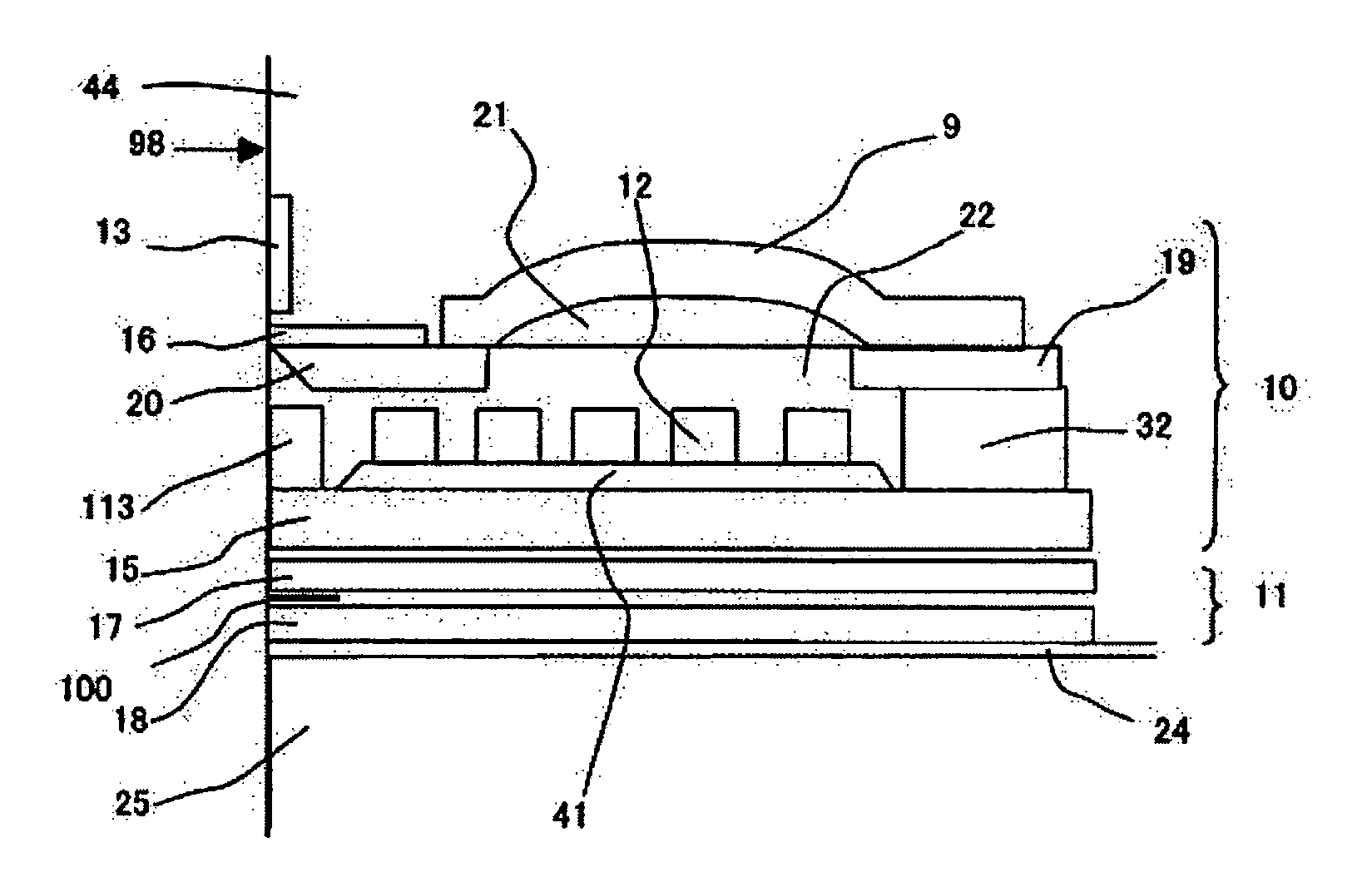
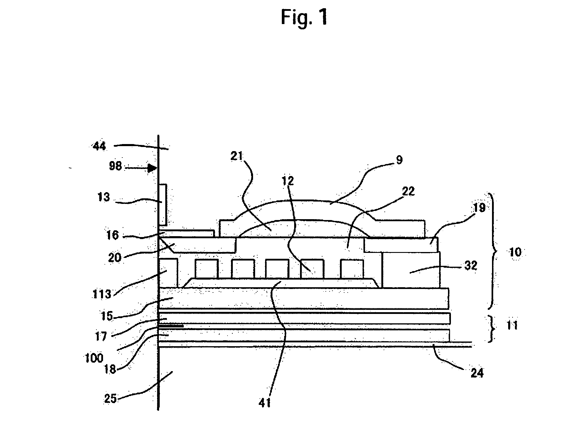
[0044] A description will be made of a structure of an information write function portion and an information read function portion mounted on the magnetic head 1. FIG. 1 is a cross sectional view of a device taken along a plane passing through the center of a main magnetic pole piece 16 and extending vertical to an air bearing surface 98. FIGS. 3 and 4 are views as viewed from the air bearing surface 98 and from the trailing side, respectively. FIG. 1 shows a structure in which a read function portion 11 and a write function portion 10 are stacked by way of a non-magnetic film over a substrate 25 of a slider.

[0045] The read function portion 11 comprises a lower shield 18, an upper shield 17 and, further, a magnetoresistive element 100 surrounded by the upper and lower shields and exposed in part to the air bearing surface. The magnetoresistive element 10019 is connected to an electrode and has a function of transmitting electric information from the read function portion to the sig...

embodiment 2

[0079] Embodiment 2 is a modified example of a structure in which the fourth magnetic film 20 in Embodiment 1 is not exposed to the air bearing surface.

[0080]FIG. 8 is a cross sectional view illustrating the constitution in which a fourth magnetic film 201 is spaced from the air bearing surface. FIG. 9 illustrates a positional relationship between a main magnetic pole piece 16 and a fourth magnetic film 201 adapted to magnetically connect a curved first magnetic film 9 and the main magnetic pole piece 16, the left figure being as viewed from the air bearing surface side and the right figure being as viewed from the trailing side. Additionally, FIG. 9 shows a relationship between the main magnetic pole piece 16 and the fourth magnetic film 201 therebelow in the widthwise-corresponding manner as viewed from the air bearing surface (on the right) and as viewed from the trailing side (on the left). While the function of the fourth magnetic film 201 has been described in Embodiment 1, a...

embodiment 3

[0083] This embodiment shows a modified example of the curved portion of the first magnetic film 9 in Embodiment 1. As a mechanism for directing the magnetic domains formed in the first magnetic film in parallel with the track width, the curved surface may be left at least on one side of the first soft magnetic film as shown in FIG. 11.

[0084] In FIG. 11, a curved surface is formed on one side of a soft magnetic film pattern 93 as a first magnetic film and a planar surface 931 is formed on the other (upper) side of the pattern 93. The first magnetic film 93 is in contact with the non-magnetic material 21 and the curvature is provided for the contact surface of the non-magnetic body 21, thereby forming the curved portion on the lower surface of the first magnetic film 93. The non-magnetic body 21 is constituted with a polymeric resin and subjected to a heat treatment.

[0085] If a shape of generating magnetic charges at a film surface is artificially prepared in a case where magnetic ...


PUM

PropertyMeasurementUnit
resistivityaaaaaaaaaa
frequencyaaaaaaaaaa
sizeaaaaaaaaaa

Abstract

Embodiments of the invention provide a perpendicular magnetic head with a narrow track and excellent high frequency characteristics. In one embodiment, a recording magnetic head includes coil conductors and magnetic pole pieces putting the same therebetween, in which a main magnetic pole piece is formed into a planar structure and a magnetic film connected with the main magnetic pole piece in a magnetic coupling relation is curved in the direction of the film thickness. Further, a shield material disposed near the main magnetic pole piece is made of a material of higher resistance than that of the material for the read shield.

Description

[0001] This application claims priority from Japanese Patent Application No. JP2005-064724, filed Mar. 9, 2005, the entire disclosure of which is incorporated herein by reference. BACKGROUND OF THE INVENTION [0002] The present invention relates to a magnetic head for use in a perpendicular magnetic recording type magnetic disk drive and, in particular, it relates to a recording magnetic head structure suitable to recording of magnetic information on a medium surface at high frequencies, as well as a manufacturing method thereof. [0003] Memory (recording) devices for information equipment mainly use semiconductor memories and magnetic memories. With a view point of access time, semiconductor memories are used for internal memory devices and, with a view point of large capacity and non-volatility, magnetic disk drives are used for external memory devices. The memory capacity is an important index for indicating the performance of the magnetic disk drive. In addition, large capacity an...

Claims


Application Information

Patent Timeline
Patent Type & Authority Applications(United States)
IPC IPC(8): G11B5/147
CPCG11B5/1278G11B5/3116G11B5/3146G11B5/3163
Inventor MARUYAMA, YOJIZAITSU, HIDEKIOHDAKE, ICHIROKUDO, KAZUEMOCHIZUKI, MASAFUMI
Owner WESTERN DIGITAL TECH INC
Why Eureka
Try Eureka