System and method for electronically identifying vehicle wheels on-the-fly during manufacture

a technology of electronic identification and vehicle wheels, applied in vehicle testing, structural/machine measurement, instruments, etc., can solve the problems of less than 100% reliable, high cost and high cost, and a difficult machine vision task, so as to achieve reliable machine identification

Inactive Publication Date: 2006-09-14
SMYTH LARRY C
View PDF23 Cites 10 Cited by
  • Summary
  • Abstract
  • Description
  • Claims
  • Application Information

AI Technical Summary

Benefits of technology

[0010] It is another object of the invention to provide a system and method for marking the vehicle wheel such that the wheel can be reliably machine-identified as it is conveyed into subsequent processes without stopping and rotating the wheel.

Problems solved by technology

For example, machining is geometry specific, and if the wrong casting is loaded, a dangerous and expensive crash occurs.
However, in higher volume automated operations, this is both expensive and less than 100% reliable.
While this is relatively straightforward for a human operator, it is a considerably more difficult task for machine vision, primarily because the snapshot is only a 2-D (two dimensional) image.
Often such systems are only effective when used in parallel with other inputs, and in some cases, series snapshots are required to eliminate the probability of misidentification.
The method is relatively expensive, cannot differentiate wheels that share much common geometry, and takes too much time for inline model identification without the massive parallelism that occurs in wheel machining.
While such lettering is readily seen in fluoroscopic images, and can be machine-recognized by optical character recognition (OCR), this technique is not a practical solution.
However, the low contrast surface makes this a more difficult task.
When low contrast bar codes are used, they are generally unreliable when read with conventional scanners.
While the system is relatively fast and reliable, it is considerably expensive and inefficient because the conveyed wheel must be stopped at the reader station and then rotated up to 360 degrees in order to locate and scan the code.

Method used


Image

  • System and method for electronically identifying vehicle wheels on-the-fly during manufacture
  • System and method for electronically identifying vehicle wheels on-the-fly during manufacture
  • System and method for electronically identifying vehicle wheels on-the-fly during manufacture

Examples


third embodiment

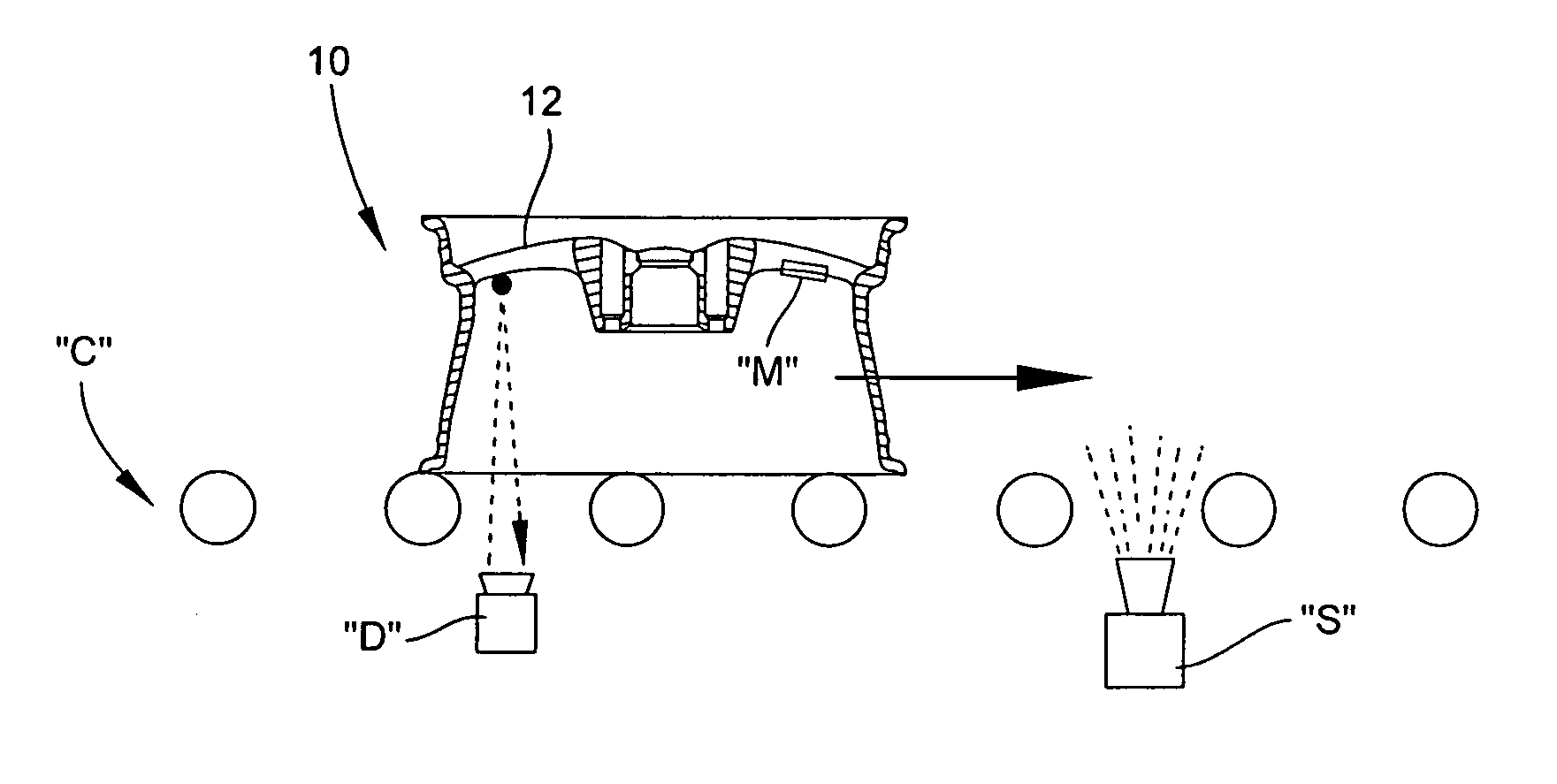
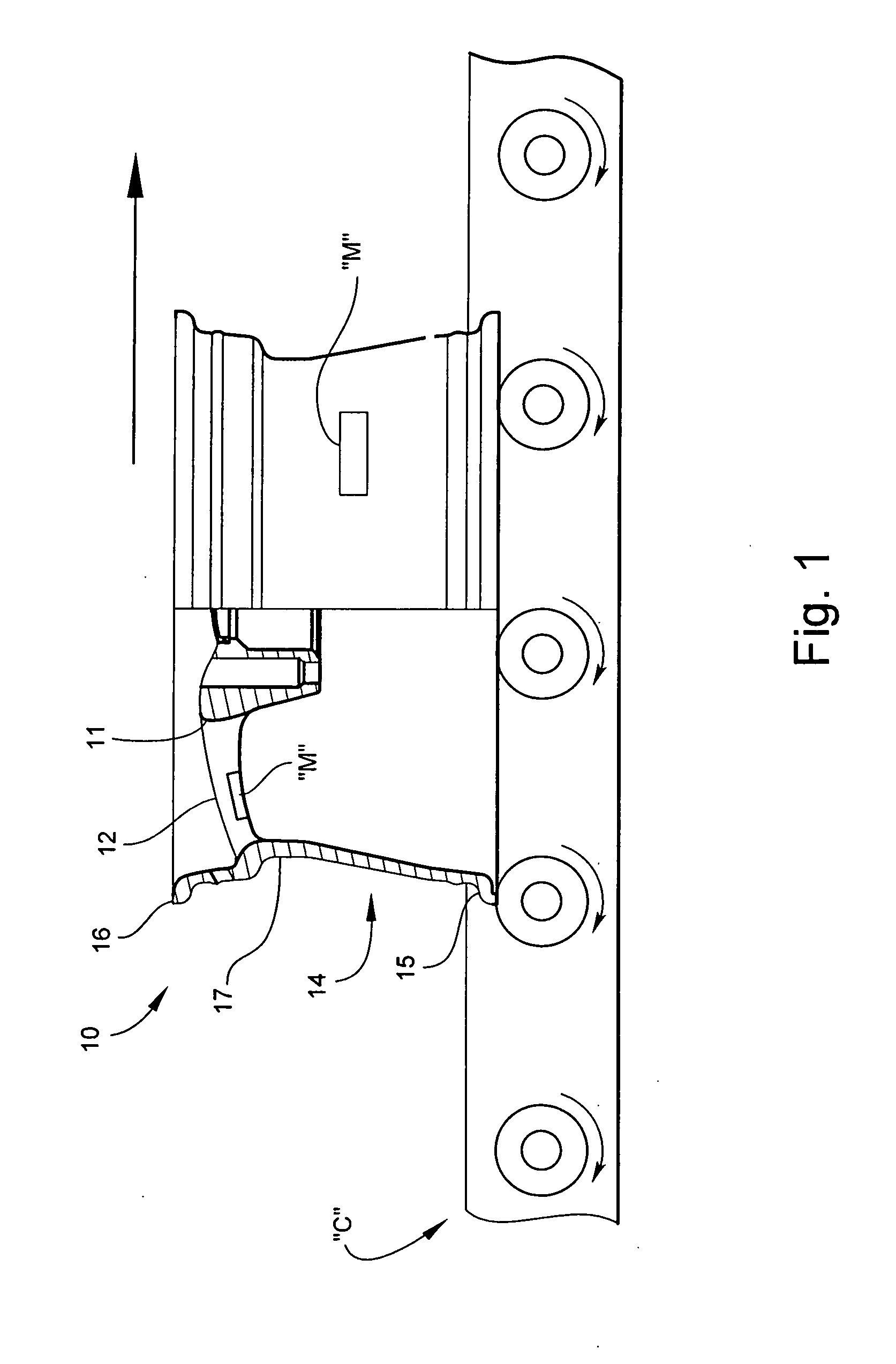
[0050] the present system is illustrated in FIGS. 6 and 7. The wheel identification mark “M” is applied to the underside of a hub spoke 12, as previously described. As the vehicle wheel 10 is moved downstream on the roller conveyor “C”, an under-mounted distance measurement device “D” determines the exact distance between the device and the underside of the hub spoke 12. Motion sensors or other suitable means (not shown) are employed to activate the device “D”. This distance measurement is then transmitted to a series of laterally-spaced scanners “S” having respective overlapping fields of view. Based on the transmitted distance, the DOF is automatically adjusted for each of the scanners “S”. As the wheel 10 passes vertically over the scanners “S”, the identification mark is electronically read by at least one of the scanners “S” and the wheel information relayed to downstream processing locations. The identification mark “M” is read by the scanner “S” on-the-fly without slowing or ...

fourth embodiment

[0051]FIG. 8 illustrates the wheel identification system. According to this embodiment, the wheel identification mark “M” is applied to an outer surface of the rim barrel 17. While moving downstream on the roller conveyor “C”, the wheel 10 enters an identification zone comprising a number of side-mounted strategically arranged scanners “S” operable for reading the entire outer circumferential surface area of the wheel 10. The identification mark “M” is located and electronically read by at least one of the scanners “S” regardless of the wheel's orientation on the roller conveyor “C”, and without slowing or stopping the wheel 10.

[0052]FIGS. 9, 9A and 10 illustrate application of the present method in a vehicle wheel 10 with eight identical, circumferentially-spaced identification marks “M” formed with its inboard flange 15. The identification marks “M” are equally spaced 45-degrees apart. As shown in FIG. 9, the scanner “S” is under-mounted below the roller conveyor “C”. As the wheel...


PUM


Abstract

The method electronically identifies a vehicle wheel on-the-fly moving downstream from one processing location to another. The method includes the steps of locating a machine-readable identification mark applied to an exposed surface of the vehicle wheel as the vehicle wheel. The identification mark is electronically read on-the-fly.

Description

TECHNICAL FIELD AND BACKGROUND OF THE INVENTION [0001] The invention relates to a system and method for electronically identifying vehicle wheels on-the-fly during manufacture. The term “manufacture” is used broadly herein to include any sequential processing of the wheel prior to its actual mounting on a vehicle. In addition to vehicle wheels, the general concept of the present invention is applicable to any other item whose identification during or after manufacture is either necessary or desirable. [0002] The manufacturing of cast alloy wheels is generally an ordered process of sequential events. Some of these events are specific to an exact wheel model, while others are not. For example, machining is geometry specific, and if the wrong casting is loaded, a dangerous and expensive crash occurs. Heat-treating, on the other hand is non-specific and the wheel model is not so important. However, as heat-treating is approximately an one shift process, it is still useful to know what i...

Claims


Application Information

Patent Timeline
Patent Type & Authority Applications(United States)
IPC IPC(8): G06F7/00G01M17/00G06FG06F17/00G07B15/02G07C3/00G08G1/01
CPCG06K7/0008G07C3/005
Inventor SMYTH, LARRY C.
Owner SMYTH LARRY C
Why Eureka
Try Eureka