Single port/multiple ring implementation of a hybrid crossbar partially non-blocking data switch

a data switch and crossbar technology, applied in the field of crossbar data switches, can solve the problems achieve the effects of low power consumption, simple control interface, and high bandwidth

Inactive Publication Date: 2006-09-14
IBM CORP +1
View PDF2 Cites 7 Cited by
  • Summary
  • Abstract
  • Description
  • Claims
  • Application Information

AI Technical Summary

Benefits of technology

[0004] The present invention provides a ring-based crossbar data switch, a method, and a computer program for transferring data between multiple bus units in a memory system. This hybrid crossbar partially non-blocking data switch is configured for a single port connection for each bus unit and multiple data rings. The data transfers on this ring-based crossbar data switch are managed by a central arbiter. Multiple data transfers on this crossbar data switch can be handled concurrently, which ensures a high bandwidth. Furthermore, unused segments of this crossbar data switch are not clocked, which results in a lower power consumption.
[0005] Each bus unit is connected to a corresponding data ramp with a simple control interface. A controller resides on each data ramp, which controls the data transfers from the data ramp to the bus unit and the data transfers between the data ramps. The central arbiter receives requests from the bus units, arbitrates the requests, and issues control signals. The controllers interpret the control signals and transfer the data accordingly. Each data ramp is only directly connected to the two adjacent data ramps, which reduces the amount of wiring resources. The data rings form the connection between all of the data ramps. This enables this ring-based crossbar data switch to transfer data from one bus unit to any other bus unit in the memory system. In a preferred embodiment, there are four data rings, wherein two data rings transfer data clockwise and two data rings transfer data counter-clockwise.

Problems solved by technology

Furthermore, unused segments of this crossbar data switch are not clocked, which results in a lower power consumption.

Method used


Image

  • Single port/multiple ring implementation of a hybrid crossbar partially non-blocking data switch
  • Single port/multiple ring implementation of a hybrid crossbar partially non-blocking data switch
  • Single port/multiple ring implementation of a hybrid crossbar partially non-blocking data switch

Examples


Embodiment Construction

[0013] In the following discussion, numerous specific details are set forth to provide a thorough understanding of the present invention. However, those skilled in the art will appreciate that the present invention may be practiced without such specific details. In other instances, well-known elements have been illustrated in block diagram form in order not to obscure the present invention in unnecessary detail. Additionally, for the most part, details concerning network communications, electro-magnetic signaling techniques, and the like, have been omitted inasmuch as such details are not considered necessary to obtain a complete understanding of the present invention, and are considered to be within the understanding of persons of ordinary skill in the relevant art.

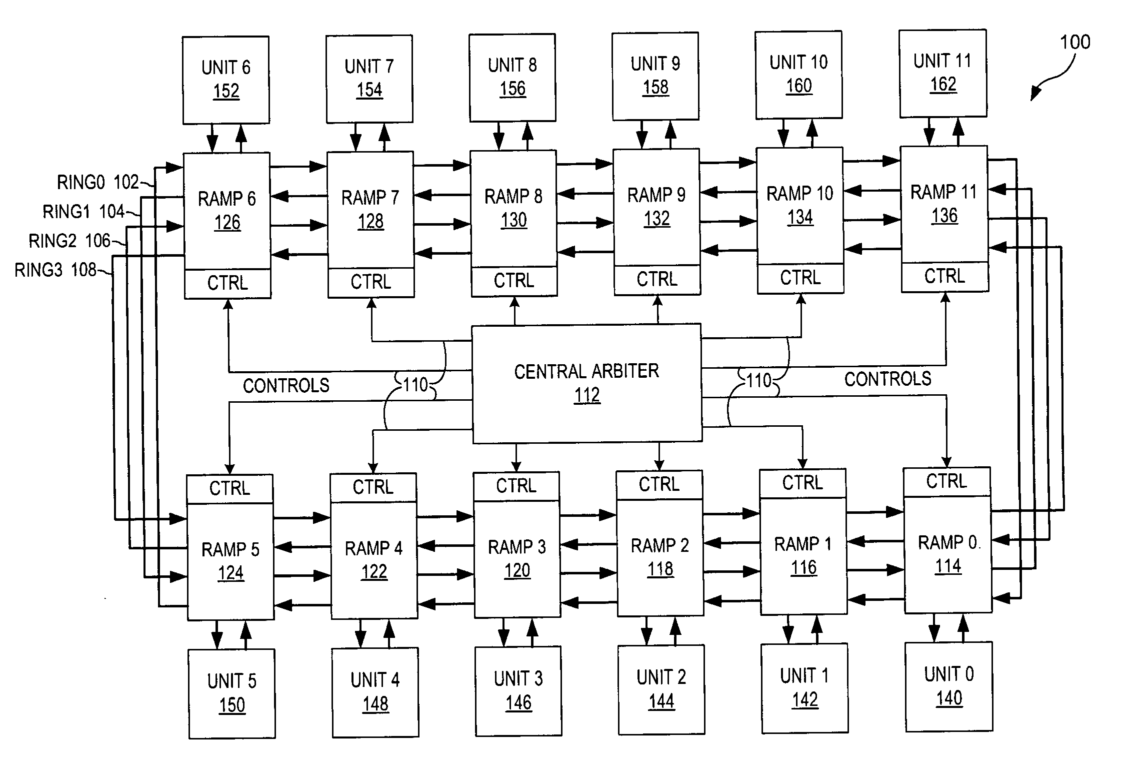
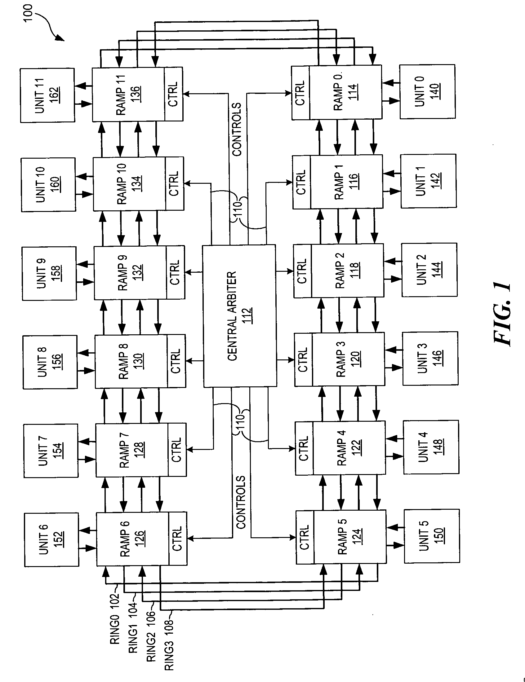
[0014] Referring to FIG. 1 of the drawings, reference numeral 100 generally indicates a block diagram of a hybrid crossbar partially non-blocking data switch with a single port / multiple ring implementation. This hybrid ...


PUM


Abstract

A ring-based crossbar data switch, a method and a computer program are provided for the transfer of data between multiple bus units in a memory system. Each bus unit is connected to a corresponding data ramp. Each data ramp is only directly connected to the adjacent data ramps. This forms at least one data ring that enables the transfer of data from each bus unit to any other bus unit in the memory system. A central arbiter manages the transfer of data between the data ramps and the transfer of data between the data ramp and its corresponding bus unit. A preferred embodiment contains four data rings, wherein two data rings transfer data clockwise and two data rings transfer data counter-clockwise.

Description

FIELD OF THE INVENTION [0001] The present invention relates generally to a crossbar data switch, and more particularly, to a hybrid crossbar partially non-blocking data switch with a single port per attached unit and multiple rings. DESCRIPTION OF THE RELATED ART [0002] The transmission of data between multiple processing units within a single chip can be difficult. This problem has become important due to the proliferation of a multiple processing units on a chip. There are many specific problems relating to the transmission of data between these units on the same chip. Data coherency, substantial area on the chip, and power consumption are a few problems with these transmissions of data. Furthermore, attempting to achieve higher transfer rates exacerbates these problems. Transfer rates can be an exceptional problem when the processing units are large enough that the time required to propagate a signal across one unit approaches the cycle time of the data bus in question. [0003] Co...

Claims


Application Information

Patent Timeline
Patent Type & Authority Applications(United States)
IPC IPC(8): G06F13/00
CPCG06F13/362G06F1/3237Y02B60/1235Y02B60/1221G06F1/3253Y02D10/00
Inventor CLARK, SCOTT DOUGLASJOHNS, CHARLES RAYKROLAK, DAVID JOHNYAMAZAKI, TAKESHIBROWN, JEFFREY DOUGLAS
Owner IBM CORP
Why Eureka
Try Eureka