Vacuum apparatus, method for measuring a leak rate thereof, program used in measuring the leak rate and storage medium storing the program

a vacuum apparatus and leakage rate technology, applied in the field of vacuum, can solve the problems of o-ring maintenance work that requires a long time, needs to be replaced frequently, and is easy to degrade, so as to reduce the downtime of the apparatus and the cost.

Inactive Publication Date: 2006-09-21
TOKYO ELECTRON LTD
View PDF5 Cites 23 Cited by
  • Summary
  • Abstract
  • Description
  • Claims
  • Application Information

AI Technical Summary

Benefits of technology

[0027] In accordance with the present invention, the leak rate of the vacuum chamber can be measured without providing a gate valve adjacent to the conductance variable valve or a gate valve integrated with the conductance variable valve (APC valve havi...

Problems solved by technology

However, in the vacuum apparatus for performing processes using a plasma, the O-ring is easily degraded by radicals generated during a dry cleaning process or the like and thus needs to be r...

Method used


Image

  • Vacuum apparatus, method for measuring a leak rate thereof, program used in measuring the leak rate and storage medium storing the program
  • Vacuum apparatus, method for measuring a leak rate thereof, program used in measuring the leak rate and storage medium storing the program
  • Vacuum apparatus, method for measuring a leak rate thereof, program used in measuring the leak rate and storage medium storing the program

Examples


Embodiment Construction

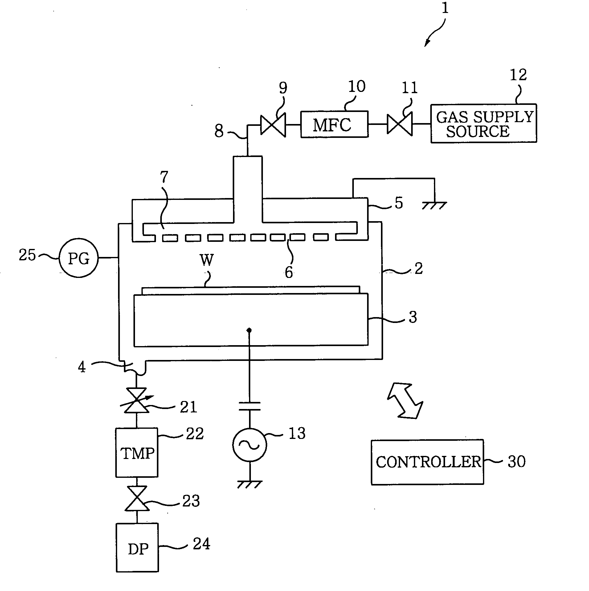
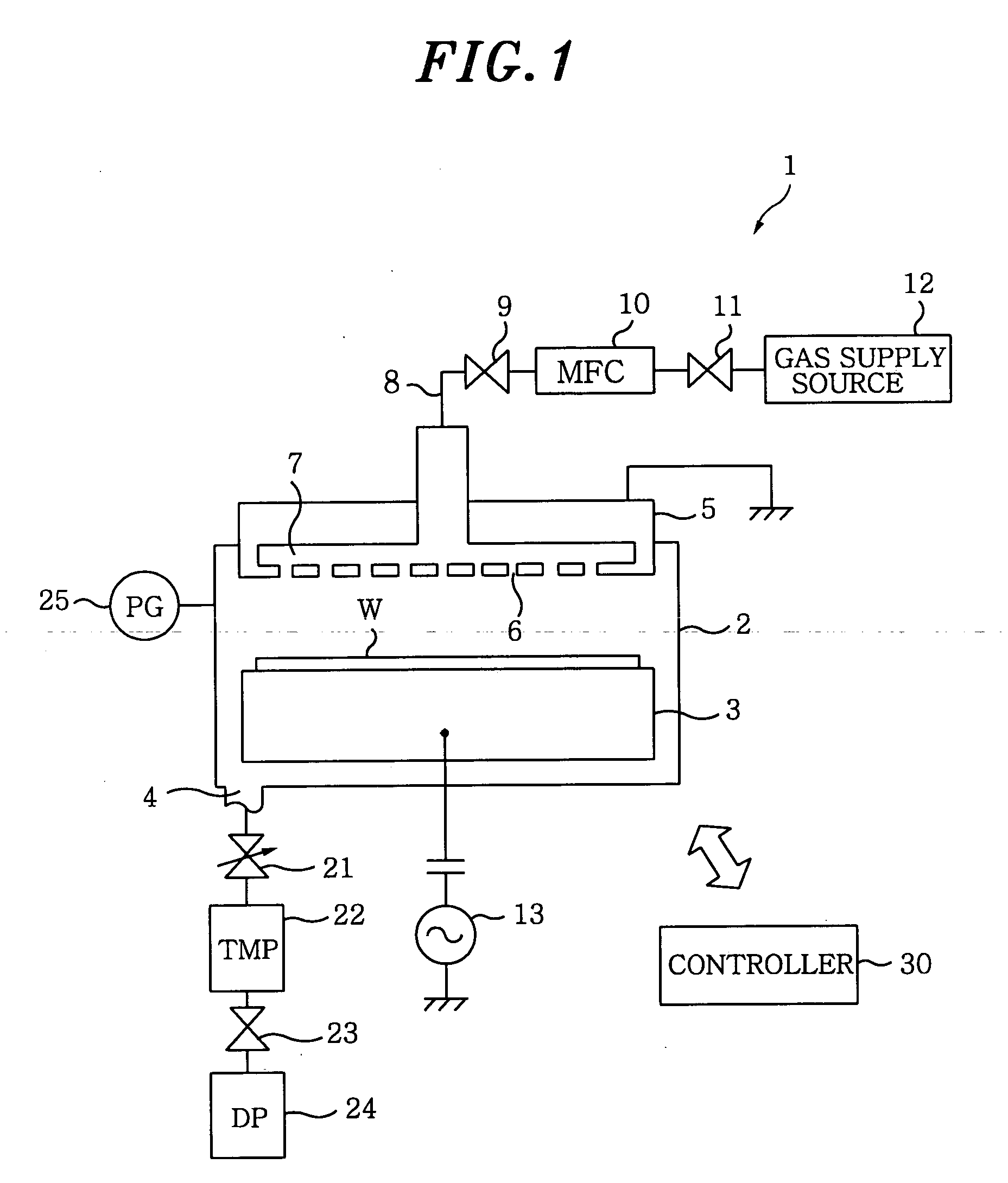
[0047] Hereinafter, preferred embodiments of the present invention will be described in detail with reference to the accompanying drawings. FIG. 1 shows a schematic view of a vacuum apparatus 1 in accordance with a first preferred embodiment of the present invention. The vacuum apparatus 1 is configured as a parallel plate type plasma processing apparatus having a pair of electrode plates vertically facing each other in parallel and is suitable for an etching process or the like in manufacturing a semiconductor device.

[0048] In a vacuum chamber 2 of the vacuum apparatus 1, there is provided a susceptor 3 serving as a lower electrode as well as a mounting table of a semiconductor wafer (hereinafter, referred to as ‘wafer’) as an object to be processed. Provided above the susceptor 3 in parallel is a grounded shower head 5 serving as an upper electrode. A gap between the susceptor 3 and the shower head 5 can be adjusted by an elevating mechanism (not shown) installed at the susceptor...


PUM


Abstract

A leak rate measuring method measures a leak rate of a vacuum apparatus including a vacuum chamber in which an object is accommodated to be processed, a first gas exhaust pump connected to the vacuum chamber via a first valve serving as a conductance variable valve, and a second valve connected to a downstream side of the first gas exhaust pump in a gas flowing direction. In the leak rate measuring method, there is provided a circulating path branched from a gas exhaust path between the first gas exhaust pump and the second valve and connected to the vacuum pump to communicate therewith. The pressure inside the vacuum chamber is monitored by circulating a gas into the vacuum chamber through the circulating path with first gas exhaust pump under the condition that the first valve is set at a predetermined conductance and the second valve is closed.

Description

FIELD OF THE INVENTION [0001] The present invention relates to a vacuum apparatus for performing an etching process, a film forming process or the like on an object to be processed such as a semiconductor wafer, a method for measuring a leak rate thereof, and a program and a storage medium used in the measurement of the leak rate. BACKGROUND OF THE INVENTION [0002] A vacuum apparatus for performing an etching process, a film forming process or the like in manufacturing various semiconductor devices includes a gas exhaust unit having a valve and a gas exhaust pump. Further, in the vacuum apparatus, a pressure inside a vacuum chamber can be depressurized to a desired vacuum state. [0003] To be specific, a conductance variable adaptive pressure control (APC) valve, a gate valve, a turbo-molecular pump (TMP) as a main gas exhaust pump, a valve and a dry pump as an auxiliary gas exhaust pump are connected to each other in that order from the side of the vacuum chamber, so that the vacuum...

Claims


Application Information

Patent Timeline
IPC IPC(8): G01M3/04
CPCG01M3/3236
Inventor KITAZAWA, TAKASHIKOBAYASHI, ATSUSHITEZUKA, KAZUYUKI
Owner TOKYO ELECTRON LTD
Why Eureka
Try Eureka