Sensor and guide wire assembly

a technology of guide wire and sensor, which is applied in the direction of instruments, catheters, angiography, etc., can solve the problems of simple reduction of chip length, occurrence of so-called bending artefacts, etc., and achieve the effect of reducing the length of the electronic part, increasing the functionality, and facilitating manufacturing

Inactive Publication Date: 2006-09-21
ST JUDE MEDICAL COORDINATION CENT
View PDF17 Cites 26 Cited by
  • Summary
  • Abstract
  • Description
  • Claims
  • Application Information

AI Technical Summary

Benefits of technology

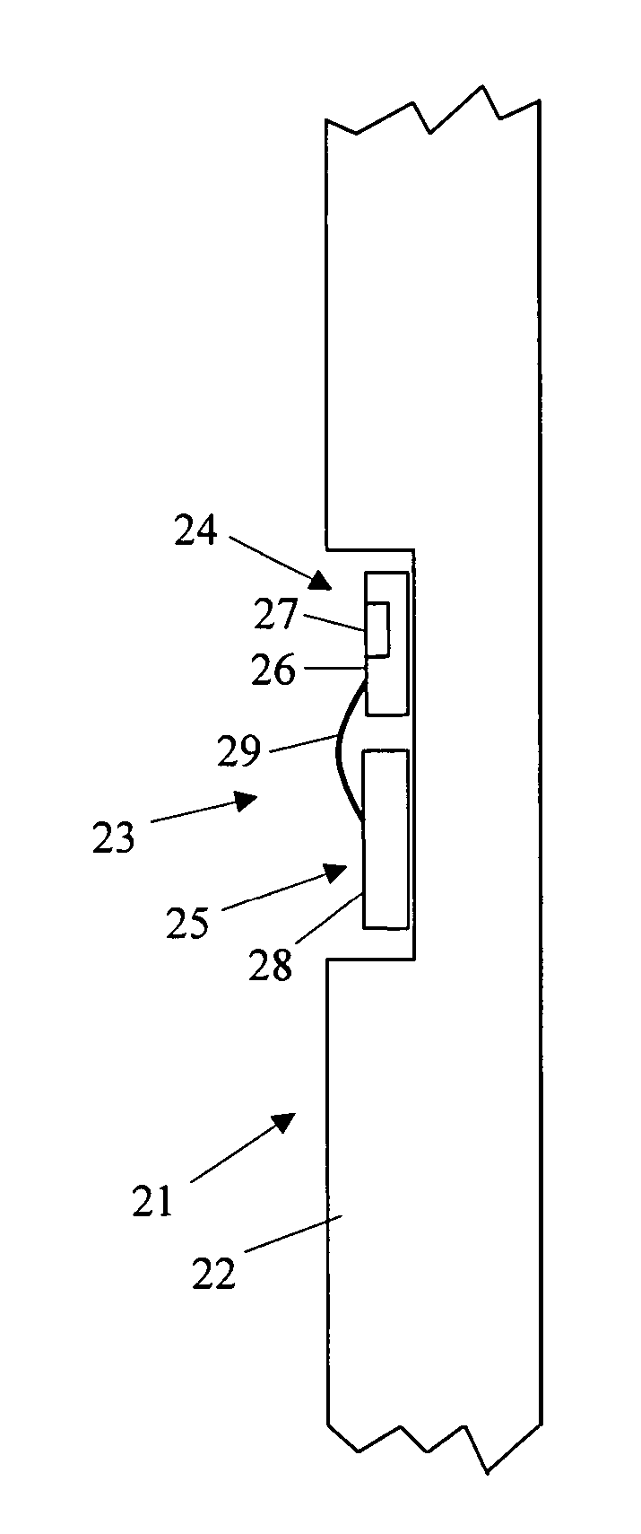
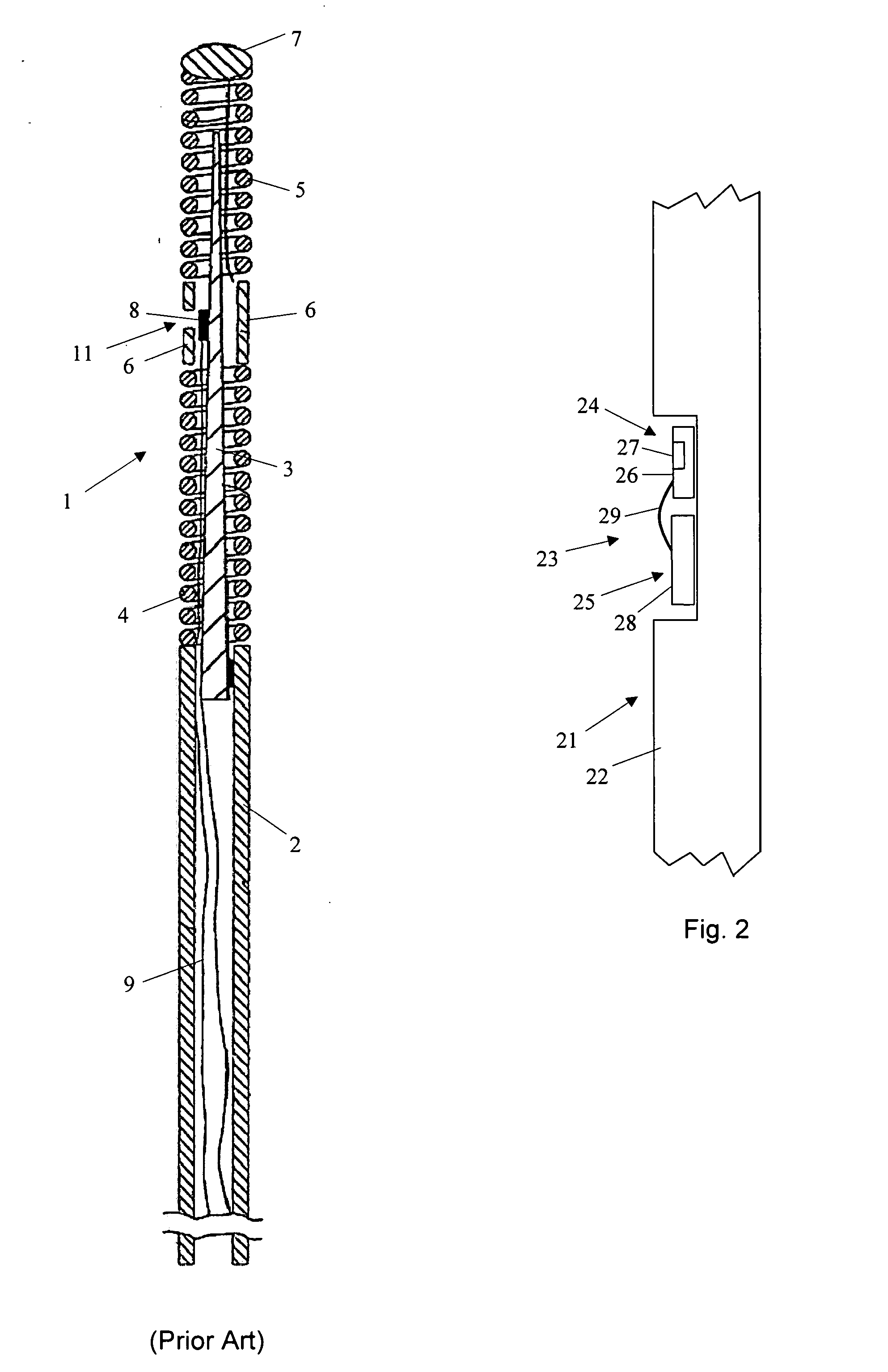
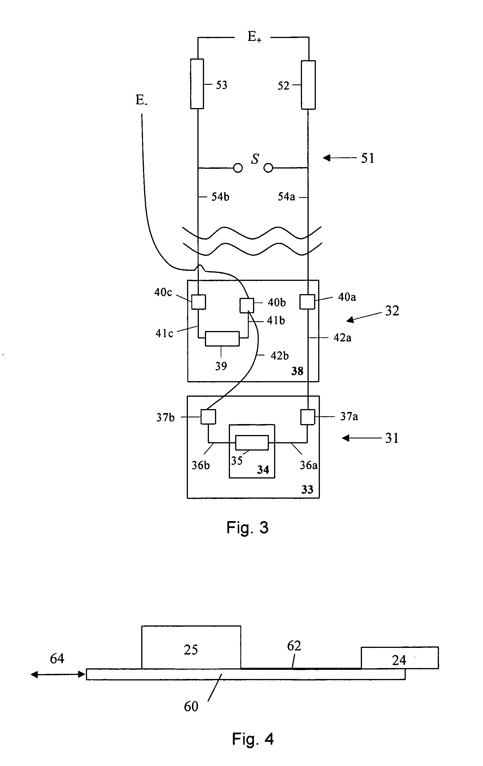
[0014] A sensor and guide wire assembly comprises a sensor which, according to the prior art, is in the form of a generally rectangular and rather thin sensor chip with a pressure sensitive device provided thereon. The pressure sensitive device can be in the form of a membrane, which covers a small cavity in the upper side at a first end portion of the sensor chip and which has piezoresistive elements mounted thereon. According to the invention, this first portion is spatially separated from a second part of the sensor. A sensor thereby comprises a pressure sensitive part, which has a pressure sensitive device, such as a membrane, provided thereon, and at least one piezoresistive element mounted on the membrane. The second part of the sensor is also referred to as the electronic part, and includes, in a first embodiment of the invention, at least one electric circuit including at least one electric resistor and connection pads. In other embodiments of the invention, the electronic part can comprise a printed circuit with electronic logic and different signal processing elements. In a sensor and guide wire assembly, the first and second parts are spatially separated with, for example, a few millimetres and are electrically connected with at least one electric lead. The length of the pressure sensitive part—which is the part of a sensor that is potentially sensitive to bending artefacts—can thereby be reduced, which, in turn, makes it less sensitive to such bending artefacts. The length of the electronic part can, on the other hand, be increased, if this is desirable in order to incorporate more functionality in the electronic circuitry arranged thereon. Another advantage with physical division of the sensor in an electronic part and a pressure sensitive part is that these two parts easily can be manufactured by different techniques and even by different manufacturers.

Problems solved by technology

As is recognized in U.S. Pat. Nos. 6,112,598 and 6,167,763, which also are assigned to the present assignee, a potential problem with this kind of guide wire mounted sensor is the occurrence of so-called bending artefacts.
To simply reduce the chip length would, however, encounter several difficulties, not least in the manufacturing process.

Method used


Image

  • Sensor and guide wire assembly
  • Sensor and guide wire assembly
  • Sensor and guide wire assembly

Examples


Embodiment Construction

[0020] For better understanding of the context in which a sensor according to the present invention is going to be used, a sensor and guide wire assembly 1 of a conventional design is illustrated in FIG. 1. The sensor guide 1 comprises a hollow tube 2, a core wire 3, a first coil 4, a second coil 5, a jacket or sleeve 6, a dome-shaped tip 7, a sensor element 8, and one or several electrical leads 9. The proximal end of the first coil 4 is attached to the distal end of the hollow tube 2, while the distal end of the first coil 4 is attached to the proximal end of the jacket 6. The proximal end of the second coil 5 is connected to the distal end of the jacket 6, and the dome-shaped tip 7 is attached to the distal end of the second coil 5. The core wire 3 is at least partly disposed inside the hollow tube 2 such that the distal portion of the core wire 3 extends out of the hollow tube 2 and into the second coil 5. The sensor element 8 is mounted on the core wire 3 at the position of the...


PUM

PropertyMeasurementUnit
length×width×heightaaaaaaaaaa
diameteraaaaaaaaaa
pressureaaaaaaaaaa

Abstract

The invention relates to a sensor (23) adapted for a sensor and guide wire assembly for intravascular measurements in a living body, wherein the sensor (23) comprises a pressure sensitive part (24) and an electronic part (25), said pressure sensitive part (24) comprising a first chip (26) provided with at least one pressure sensitive device (27) and at least one piezoelectric element (35), and said electronic part (25) comprising a second chip (28) provided with at least one electric circuit, and wherein said pressure sensitive part (24) and electronic part (25) are spatially separated from each other and are electrically connected with at least one electrical lead (29).

Description

FIELD OF THE INVENTION [0001] The present invention relates generally to sensor and guide wire assemblies, in which a sensor is mounted at the distal end of a guide wire for intravascular measurements of physiological variables in a living body, and in particular to the design and arrangement of the sensor. BACKGROUND OF THE INVENTION [0002] Sensor and guide wire assemblies in which a sensor is mounted at the distal end of a guide wire are known. In U.S. Pat. No. Re. 35,648, which is assigned to the present assignee, an example of such a sensor and guide wire assembly is disclosed, where a sensor guide comprises a sensor element, an electronic unit, a signal transmitting cable connecting the sensor element to the electronic unit, a flexible tube having the cable and the sensor element disposed therein, a solid metal wire (also called a core wire), and a coil attached to the distal end of the solid wire. The sensor element comprises a pressure sensitive device, e.g. a membrane, with ...

Claims


Application Information

Patent Timeline
Patent Type & Authority Applications(United States)
IPC IPC(8): G01L9/00A61B5/0215A61M25/09
CPCA61B5/0215A61B5/6851A61M25/09A61M2025/0166A61M2025/09083G01L9/0022G01L9/06G01L19/142G01L19/147H01L2224/48091H01L2224/48137H01L2924/00014
Inventor TENERZ, LARSSMITH, LEIF
Owner ST JUDE MEDICAL COORDINATION CENT
Why Eureka
Try Eureka