Method of dynamically controlling open hole pressure in a wellbore using wellhead pressure control

a wellhead pressure control and open well technology, applied in the direction of wellbore/well accessories, earth drilling and mining, chemistry apparatus and processes, etc., can solve the problems of increasing the cost of drilling operations, overbalancing the situation, and the effect of high formation pressure on the success of only limited effects

Active Publication Date: 2006-09-21
WEATHERFORD CANADA
View PDF42 Cites 115 Cited by
  • Summary
  • Abstract
  • Description
  • Claims
  • Application Information

AI Technical Summary

Benefits of technology

[0009] The invention therefore provides a method of dynamically controlling open hole pressure in a wellbore that addresses a number of limitations in the prior art. In particular, the method of the present invention provides a simplified, efficient and relatively inexpensive manner to dynamically control open hole pressure during a drilling operation through the application of wellhead pressure.

Problems solved by technology

Due to the potential danger of a blowout in high pressure wells, in most instances an overbalanced situation is desired with the hydrostatic head of the drilling mud exceeding the underground formation pressure by a predetermined safety factor.
Unfortunately, such prior systems that employ high density drilling muds to counterbalance the effects of high formation pressures have met with only limited success.
In order to create a sufficient hydrostatic head, the density of the drilling mud often has to be relatively high (for example from 15 to 25 pounds per gallon), necessitating the use of costly density enhancing additives.
Such additives not only significantly increase the cost of the drilling operations, but can also present environmental difficulties in terms of their handling and disposal.
High density muds may also not be compatible with many standard surface separation systems that are commonly in use.
High density drilling muds also present an increased potential for plugging downhole components, particularly where the drilling operation is unintentionally suspended due to mechanical, electrical, hydraulic or other failure.
In addition, the high hydrostatic pressure created by the column of drilling mud in the string often results in a portion of the mud being driven into the formation, requiring additional fresh mud to be continually added at the surface and thereby further increasing costs.
Invasion of the drilling mud into the subsurface formation may also cause irreparable damage to the formation.
Another limitation of such prior well pressure systems concerns the degree and level of control that may be exercised over the well.
For that reason there is only a limited ability to alter the hydrostatic pressure applied to the formation.
The former can be an expensive and time consuming process, and the latter is limited and not always practical since it may have an adverse affect on the ability to clean the hole.
While friction pressure methods of this sort may be effective in controlling bottom hole pressure, they can also increase the level of complexity of the overall drilling process, and necessitate the use of additional equipment that can have the result of increasing both capital and operating costs.
As in the case of friction pressure systems, current surface back pressure systems add a significant level of complexity to the drilling operations, necessitate the use of additional equipment, and to a large extent are dependent upon the accuracy and predictability of a constantly changing downhole pressure model.
Neither friction pressure nor currently available surface back pressure systems are designed to specifically counteract the effects of surge and swab pressures caused by the movement of the drill string.

Method used


Image

  • Method of dynamically controlling open hole pressure in a wellbore using wellhead pressure control
  • Method of dynamically controlling open hole pressure in a wellbore using wellhead pressure control
  • Method of dynamically controlling open hole pressure in a wellbore using wellhead pressure control

Examples


Embodiment Construction

[0026] The present invention may be embodied in a number of different forms. The specification and drawings that follow describe and disclose only some of the specific forms of the invention and are not intended to limit the scope of the invention as defined in the claims that follow herein.

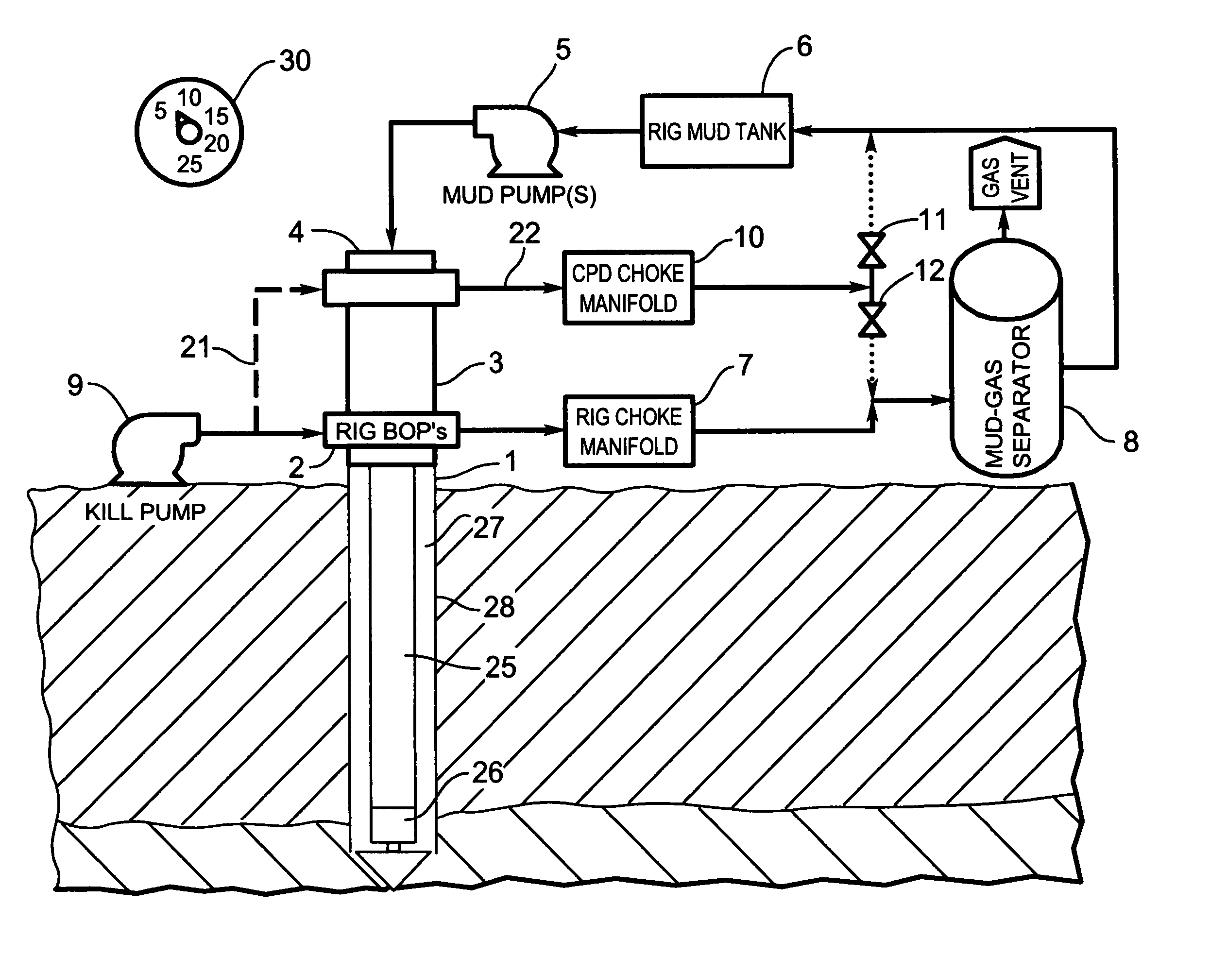
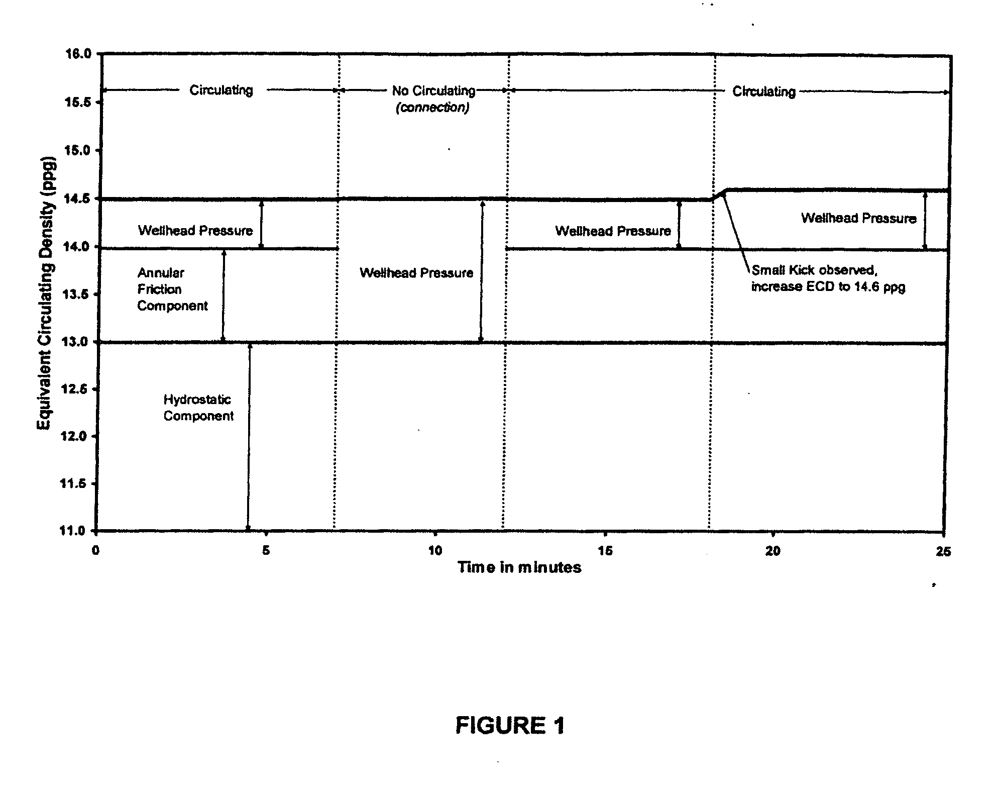
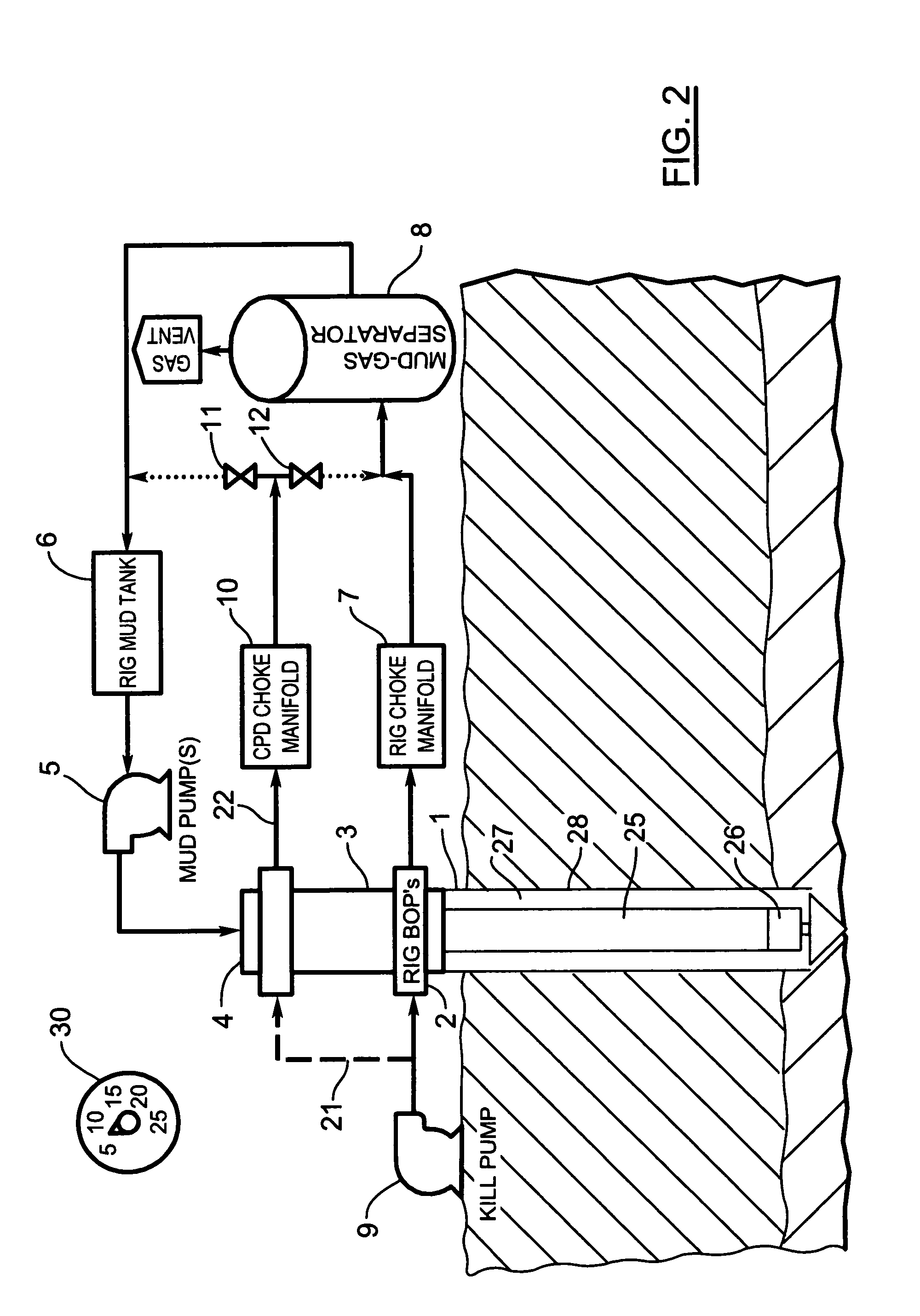
[0027] The method of controlling open hole pressure according to the present invention in one aspect generally involves controlling the effective hole pressure gradient by replacing or augmenting the frictional component of hole pressure with wellhead or back pressure. Open hole pressure can be defined mathematically by the following general relationship:

POH=PHyd+PFric+PWH; where,[0028] POH is open hole pressure; [0029] PHyd is hydrostatic pressure; [0030] PFric, is friction pressure; and, [0031] PWH is wellhead pressure.

[0032] In FIG. 1 there is shown graphically the relationship between hole pressure, hydrostatic pressure, friction pressure and wellhead pressure in the case of a circulating a...


PUM


Abstract

A method of dynamically controlling open hole pressure within a wellbore having a drill string positioned therein. The method comprising the steps of pumping a fluid down the drill string, into an annulus formed by the drill string and the interior of the wellbore, and then subsequently up the annulus to the surface of the ground; selectively applying wellhead pressure to the annulus through selectively pumping an additional quantity of the fluid or a quantity of a secondary fluid across the annulus; and, controlling the application of wellhead pressure applied to the annulus by controlling one, or both, of (a) the operation of a wellhead pressure control choke, and (b) the flow rate of the additional quantity of fluid or the secondary fluid pumped across the annulus, to thereby maintain open hole pressure within a desired range.

Description

FIELD OF THE INVENTION [0001] This invention relates to a method of controlling open hole pressure in a wellbore while drilling through underground formations. In one of its embodiments the invention pertains to a method of dynamically controlling open hole pressure through the use of wellhead pressure control. BACKGROUND OF THE INVENTION [0002] Common methods of drilling wells from the surface down through underground formations employ the use of a drill bit that is rotated by either a downhole motor (sometimes referred to as a mud motor), through rotation of a drill string extending from the surface, or through a combination of both surface and downhole drive mechanisms. Where a downhole motor is utilized, energy is typically transferred from the surface to the downhole motor by pumping a drilling fluid or “mud” down through a drill string and channeling the fluid through the motor causing the rotor of the downhole motor to rotate and drive the rotary drill bit. The drilling fluid...

Claims


Application Information

Patent Timeline
Patent Type & Authority Applications(United States)
IPC IPC(8): E21B44/00
CPCE21B21/08E21B21/106E21B44/00
Inventor KINDER, JOEGRAHAM, ROBERT
Owner WEATHERFORD CANADA
Why Eureka
Try Eureka