
Efficient high-speed electric device using low-loss materials

a high-speed, low-loss technology, applied in the direction of dynamo-electric machines, magnetic circuit rotating parts, magnetic circuit shapes/forms/construction, etc., can solve the problems of little success in building such machines of axial or radial air gap type, and achieve high efficiency, small core loss, and increased power

Inactive Publication Date: 2006-09-21
BERG & BERG ENTERPRISES
View PDF21 Cites 42 Cited by
  • Summary
  • Abstract
  • Description
  • Claims
  • Application Information

AI Technical Summary

Benefits of technology

[0014] The stator assembly of the present device has a magnetic core made from low loss, high frequency material. Preferably, the stator's magnetic core is made of advanced, low core loss soft magnetic material. Representative examples of such material include certain amorphous metals, nanocrystalline metals, and optimized Fe-based alloys. The latter are crystalline materials that may be either grain-oriented or non-grain-oriented materials. Preferred, advanced, low-loss soft-magnetic materials are characterized by a core loss less than “L” where L is given by the formula L=12·f·B1.5+30·f2.3·B2.3, where L is the loss in W / kg, f is the frequency in KHz, and B is the peak magnetic flux density in Tesla. The use of one or more of these materials enables the device's excitation frequency to be increased above 400 Hz with only a relatively small increase in core loss, as compared to the large increase exhibited in conventional machines. The resulting device is highly efficient and capable of providing increased power.
[0015] In an aspect, the invention provides a highly efficient electric device with a high pole count capable of providing increased power density, improved efficiency, and a more square torque-speed curve. A preferred embodiment of the present device employs an axial-airgap configuration comprising at least one stator assembly including a unitary magnetic core having a number of slots. The slots are wound with stator windings. The electromagnetic device also includes at least one rotor assembly including a plurality of rotor poles. The rotor assembly is arranged and disposed for magnetic interaction with the at least one stator. The electromagnetic device is preferably capable of operating continuously under excitation at frequencies higher than 400 Hz.

Problems solved by technology

While it is generally believed that motors and generators having rotors constructed with advanced permanent magnet material and stators having cores made with advanced, low-loss soft materials, such as amorphous metal, have the potential to provide substantially higher efficiencies and power densities compared to conventional radial airgap motors and generators, there has been little success in building such machines of either axial or radial airgap type.

Method used


Image

  • Efficient high-speed electric device using low-loss materials
  • Efficient high-speed electric device using low-loss materials
  • Efficient high-speed electric device using low-loss materials

Examples


example 6

Configuration and Properties of a Dynamoelectric Machine of the Invention

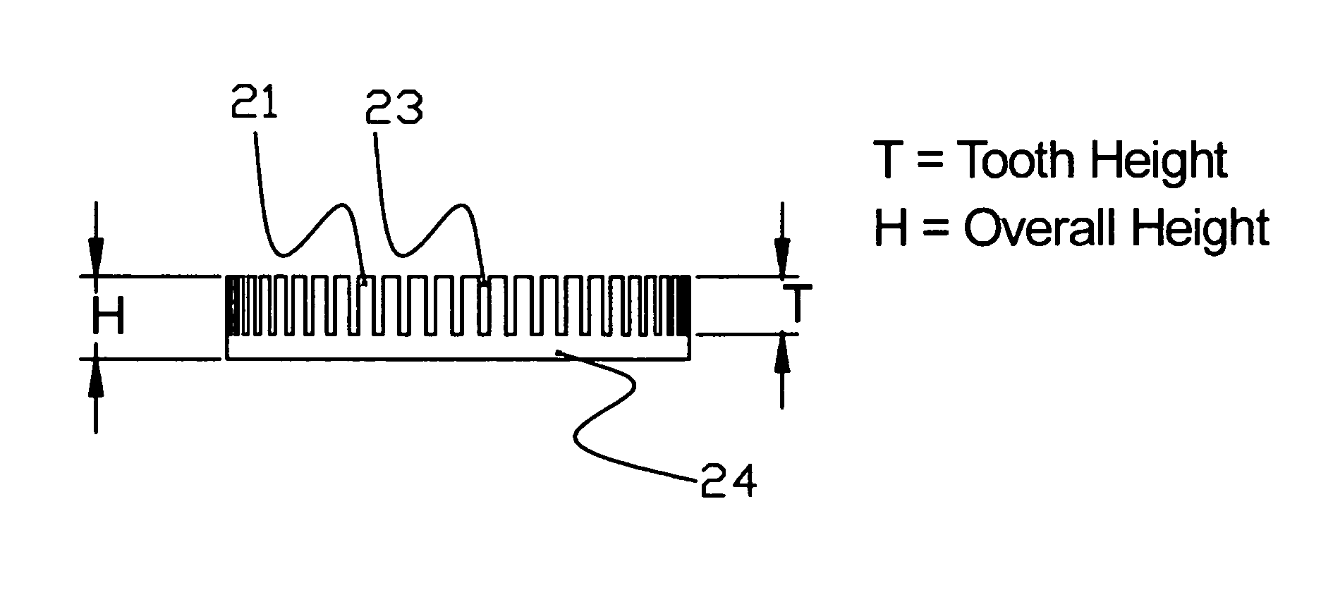
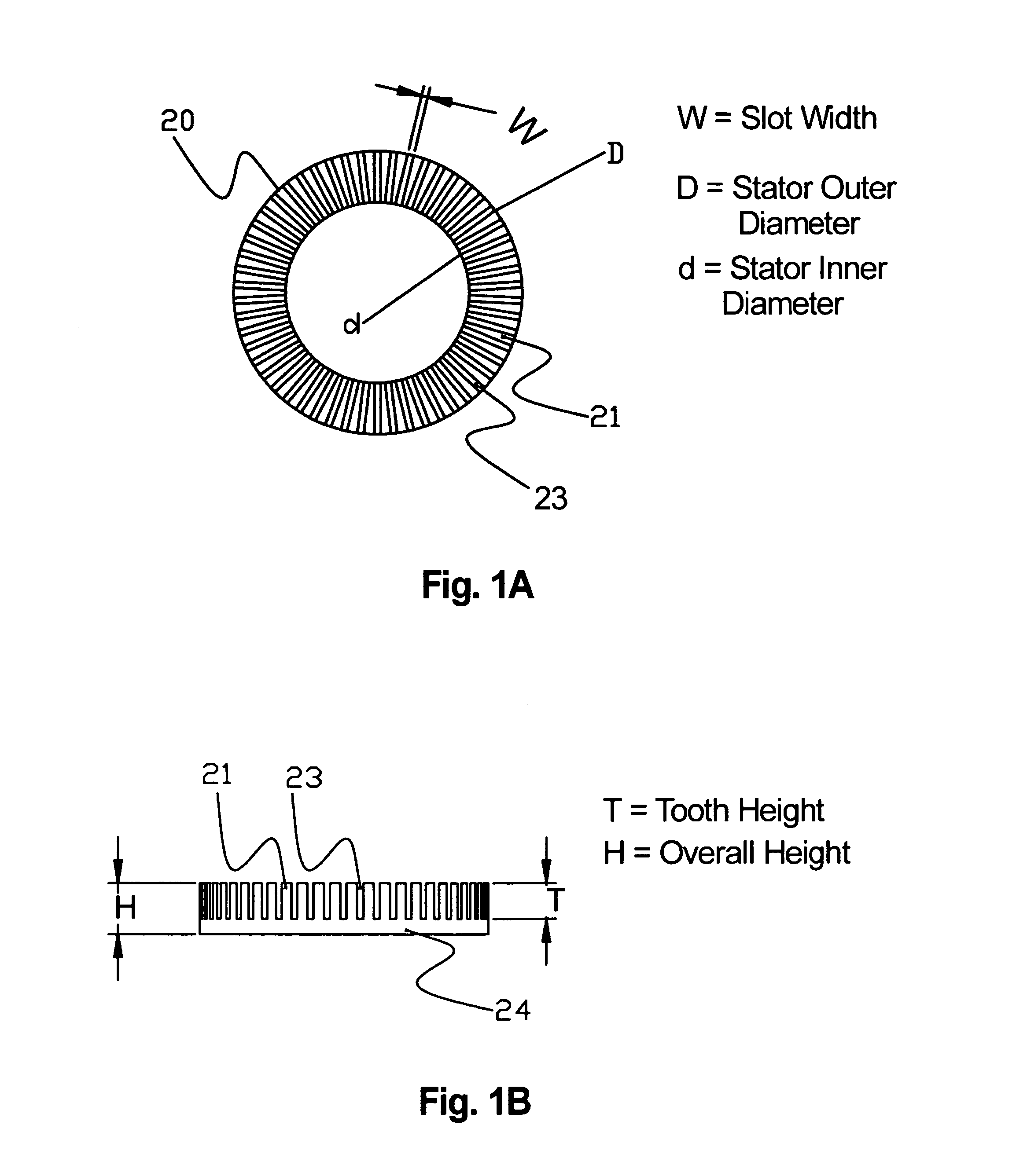
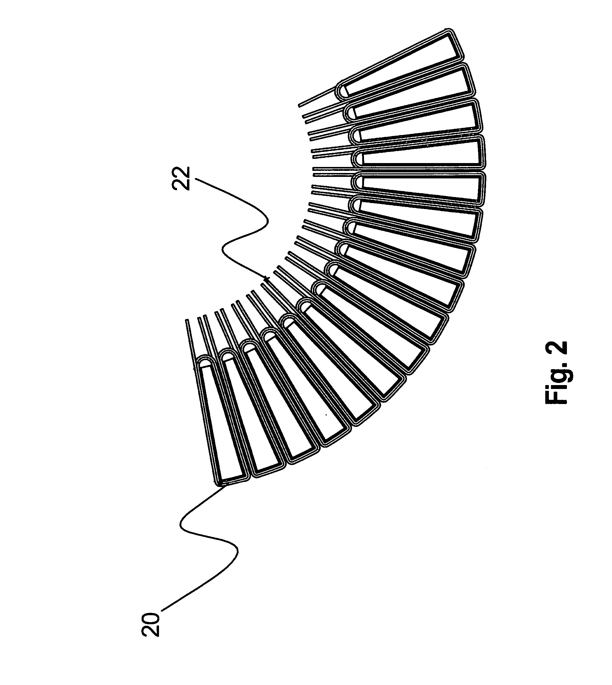
[0155] A three-phase axial airgap motor (Example 6) is designed according to the concepts described above. The magnetic stator core of the motor is formed from Metglas® alloy 2605SA1, and is slotted with 54 equally spaced teeth. The stator winding is a single layer of 26+ / −1 turns of a coil with resistance of about 0.011 Ω at room temperature. The rotor assembly is constructed using 36 rotor magnets composed of a rare earth-iron-boron magnet alloy having a maximum energy product greater than 36 MGOe and an intrinsic coercive field greater than 21 kOe. The magnets are approximately 65×14×8 mm in size and are magnetized along the 8 mm dimension. They are arranged with alternating polarity in a rotor plate. Representative performance characteristics of this electric machine operated in motoring mode using suitable power electronics are set forth in Table IV below.

TABLE IVExemplary Performance Of A Dynamoelectri...

examples 7-13

Design and Characterization of Dynamoelectric Machines of the Invention

[0161] Several exemplary electric machines designed in accordance with the present invention are set forth in Table VI below, along with the machine of Comparative Example 7. Each of these machines has an axial air gap, 3-phase configuration having the slot number stated in column 5 and an SPP of 0.5. The synchronous frequency ratio is as listed in column 2. The overall active material radius and axial length are shown in columns 3 and 4. The FeNdB magnetic material used in each machine has a nominal 39 MGOe energy product. The Comparative Example 7 machine uses conventional M19 SiFe motor laminations, whereas Examples 7 through 13 use advanced soft magnetic material as described herein.

TABLE VIDynamoelectric Machine ConfigurationsKfActiveActive(Hz perActiveActiveSlotsMaterialSurfaceExam-1000RadiusLengthperMassAreaλplerpm)(mm)(mm)Stator(kg)(cm2)(IR / OR)Comp. 100144.2149.2183426590.60Ex. 7 730097.880.254810940.6...


PUM


Abstract

The invention relates generally to an electric device, such as an electric motor, a generator, or a regenerative motor, having a wound stator core made from advanced low-loss material. In preferred embodiments, the electric device is an axial airgap-type configuration. The invention provides an electric device having a high pole count that operates at high commutating frequencies, with high efficiency and high torque and power densities. Advanced low-loss materials exploited by the present invention include amorphous metals, nanocrystalline metals, and optimized Fe-based alloys.

Description

CROSS-REFERENCE TO RELATED APPLICATIONS [0001] This application is a continuation-in-part of U.S. patent application Ser. No. 10 / 769,094, filed Jan. 30, 2004, and further claims the benefit of U.S. Provisional Patent Application Ser. Nos. 60 / 444,271 and 60 / 513,892, filed Jan. 31, 2003 and Oct. 21, 2003, respectively, each of which application is hereby incorporated herein in its entirety by reference thereto.BACKGROUND OF THE INVENTION [0002] 1. Field of the Invention [0003] The invention relates to an electric device; and more particularly, to a rotating dynamoelectric machine capable of operating at high commutating frequencies, with high efficiency and high power and torque densities. [0004] 2. Description of the Prior Art [0005] The electric motor and generator industry is continuously searching for ways to provide motors and generators with increased efficiencies and power densities. The power of an electromagnetic device is related to the exciting frequency of the device (also...

Claims


Application Information

Patent Timeline
Patent Type & Authority Applications(United States)
IPC IPC(8): H02K1/00H02K1/22H02K1/02H02K21/24
CPCH02K1/02H02K21/24H02K1/22H02K15/02
Inventor HIRZEL, ANDREW D.
Owner BERG & BERG ENTERPRISES
Learn More