
Efficient high-speed electric device using low-loss materials

Inactive Publication Date: 2006-06-27
BERG & BERG ENTERPRISES
View PDF19 Cites 40 Cited by
  • Summary
  • Abstract
  • Description
  • Claims
  • Application Information

AI Technical Summary

Benefits of technology

[0012]An electro-magnetic device as disclosed herein includes a magnetic field assembly, such as a rotor, and a stator assembly. The stator assembly has a magnetic core made from low loss, high frequency material. Preferably, the stator's magnetic core is made of amorphous metals, nanocrystalline metals, optimized Si—Fe alloys, grain-oriented Fe-based materials or non-grain-oriented Fe-based materials. The introduction of amorphous metals, nanocrystalline metals, optimized Si—Fe alloys, grain-oriented Fe-based materials or non-grain-oriented Fe-based materials into electrical devices enables the device's frequency to be increased above 300 Hz with only a relatively small increase in core loss, as compared to the large increase exhibited in conventional machines, thus yielding a highly efficient electric device capable of providing increase power. The invention provides a highly efficient electric device with a high pole count capable of providing increased power density, improved efficiency, and a more square torque-speed curve.

Problems solved by technology

However, it is significant to note that as the pole count increases, the changes in the magnetic field for the machine also increase, and additional heat is generated within the machine, thereby contributing to the inefficiency of the machine.
However, the significant core losses seen with conventional higher pole machines is mainly due to the fact that the material used in the vast majority of old machines is a conventional silicon-iron alloy (Si—Fe), which contains about 3½% or less by weight of silicon.
In particular, losses resulting from the changing magnetic fields at frequencies greater than about 300 Hz in conventional Si—Fe-based materials causes the material to heat to the point where the device cannot be cooled by any acceptable means.
Accordingly, a commercially viable high frequency electric machine has been difficult to achieve, and therefore it would be desirable to produce a commercially viable high frequency electric machine.
However, previous attempts at incorporating amorphous material into conventional machines failed since these attempts simply involved substituting amorphous material for the silicon-iron in conventional magnetic cores of lower frequency electric machines.
This resulted in electric machines having increased efficiencies with less loss, but with a subsequent loss in power output and significant increases in cost associated with handling and forming the amorphous material.
Notwithstanding significant study surrounding the use of amorphous metals in electric machines, to date it has proven very difficult to cost effectively provide a readily manufacturable electric device, which takes advantage of low loss materials, and many have abandoned attempts to develop a commercially viable electric machine having a magnetic core of amorphous metal.

Method used


Image

  • Efficient high-speed electric device using low-loss materials
  • Efficient high-speed electric device using low-loss materials
  • Efficient high-speed electric device using low-loss materials

Examples


example

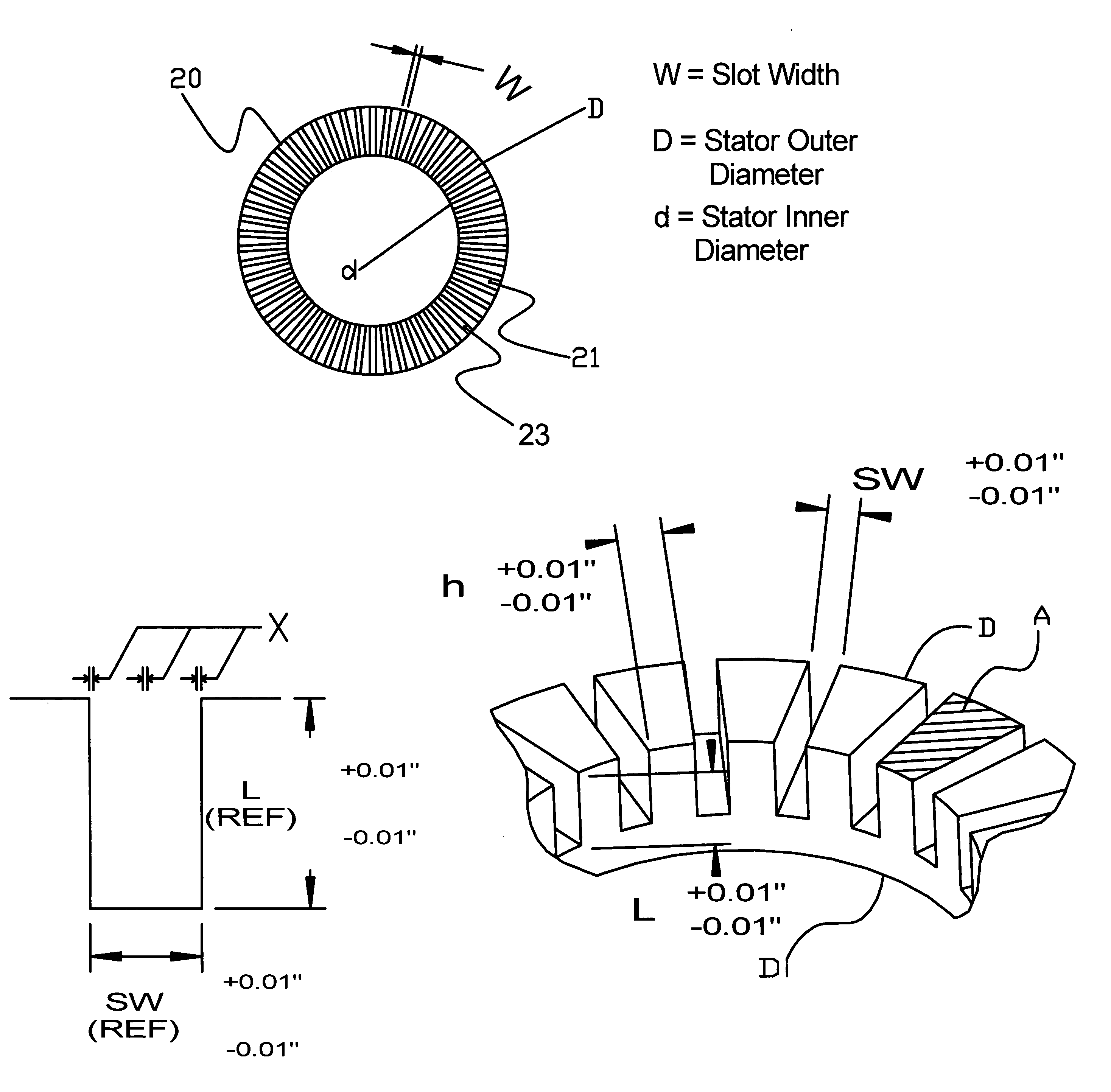
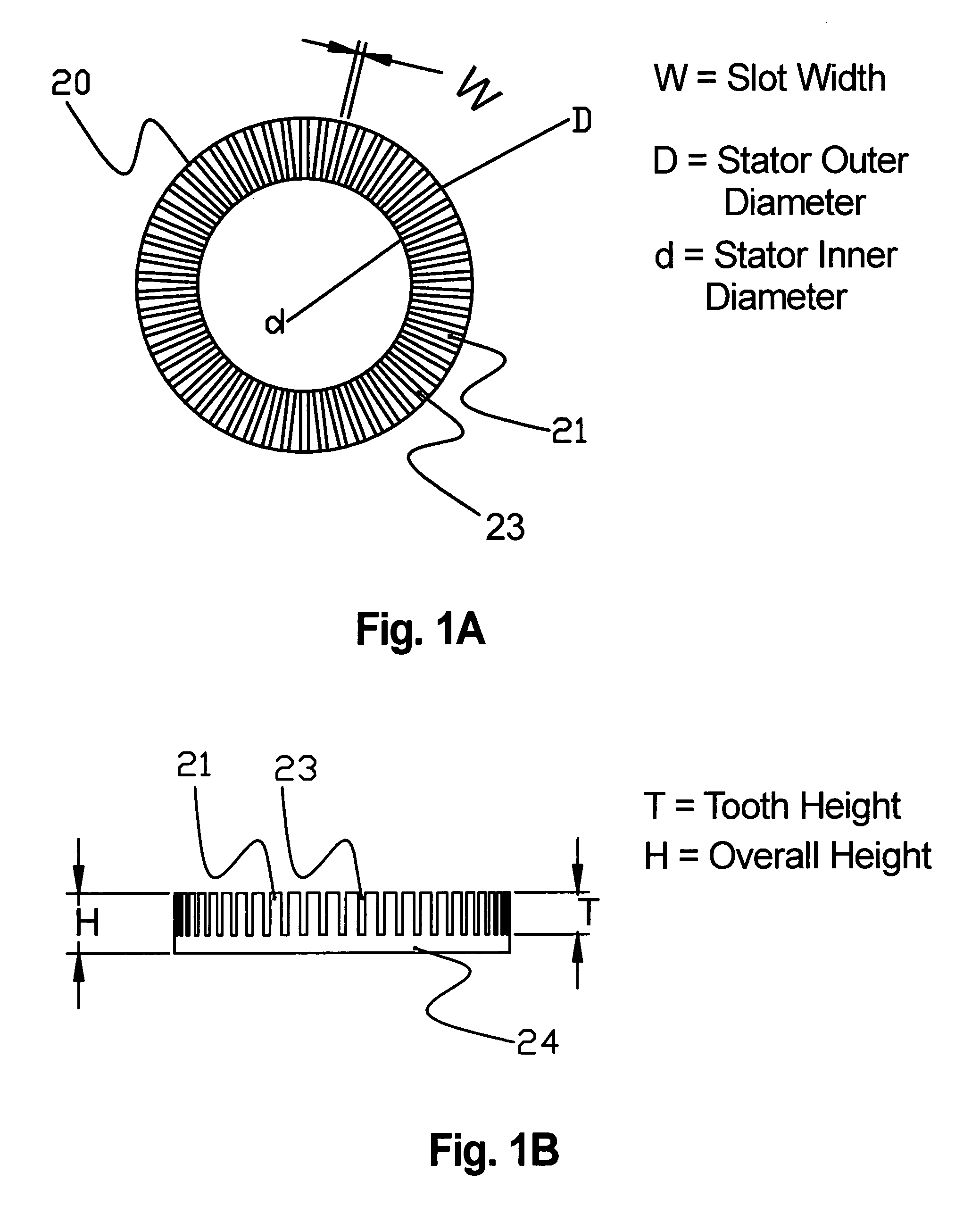
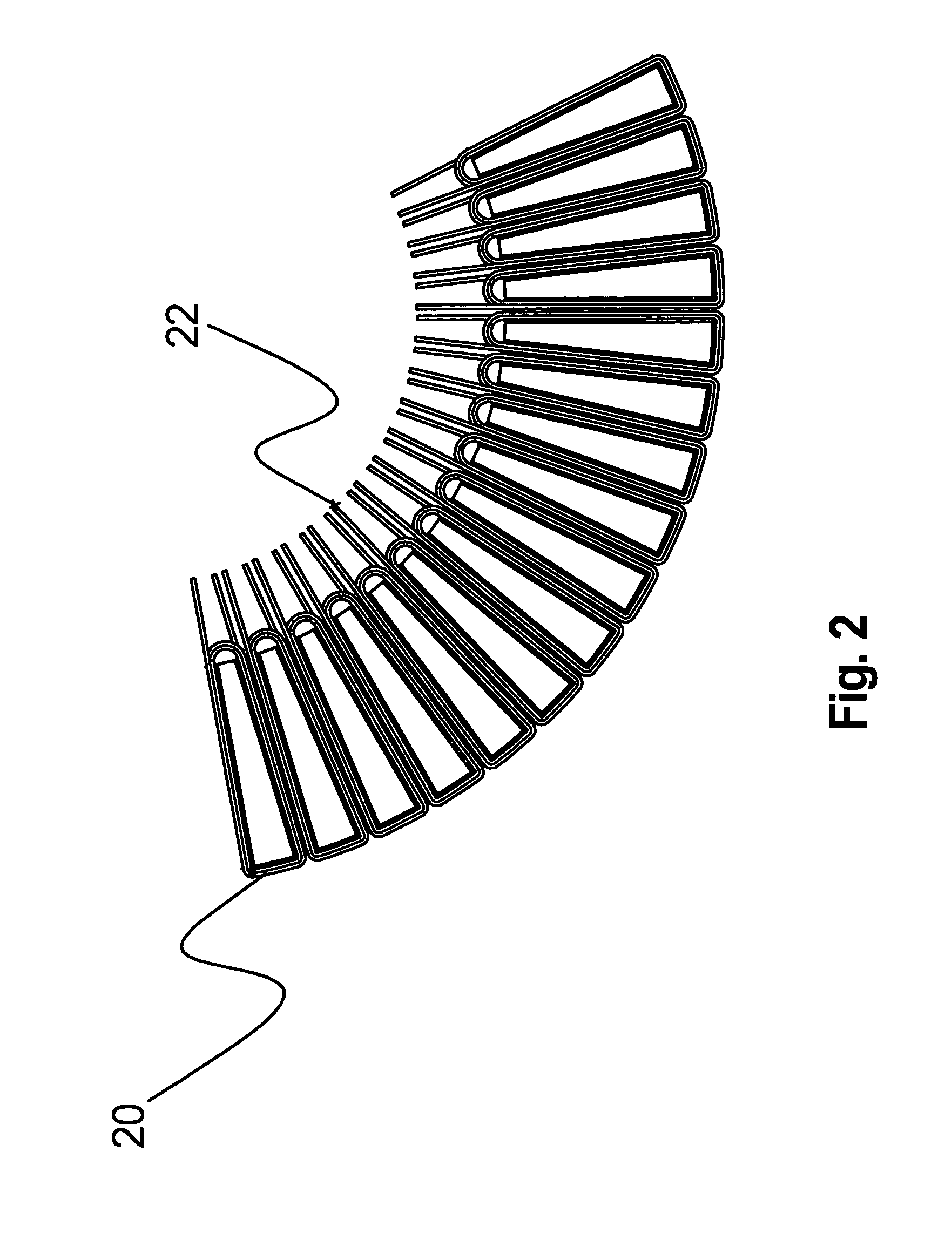
[0124]A motor has been designed according to the electric machine concepts described above. The magnetic core of the motor was formed from Metglas® alloy 2605SA1, and is slotted with 54 equally spaced teeth. The stator winding is a single layer of 26+ / −1 turns of a coil with resistance of about 0.011 Ω at room temperature. The rotor assembly was constructed from 36 rotor magnets arranged with alternating polarity in a rotor plate. The rotor magnets are rare earth / iron / boron magnets with maximum energy product greater than 36 MGOe and intrinsic coercive force greater than 21 kOe. Performance characteristics of this electric machine are set forth table 4 below:

[0125]

TABLE 4EXEMPLARY PERFORMANCEInverter320Vrms lineReal Output Power80852WattsShaft torque214N-mSpeed3600rpmEfficiency94%Machine CoolingLiquidPole Pairs18Slots per Stator54Overall Machine SizeOutside Diameter308mmLength117mmElectrical, Phase PropertiesKe66Vrms / krpm lineKe0.363V-sTHD of Ke2.9%Resistance11.8m-ohmInductance85.8u...


PUM


Abstract

The invention relates generally to an electric device, such as an electric motor, a generator, or a regenerative motor, having a wound stator core made from advanced low-loss material. In preferred embodiments, the electric device is an axial airgap-type configuration. The invention provides an electric device having a high pole count that operates at high commutating frequencies, with high efficiency and high power density. Advanced low-loss materials exploited by the present invention include amorphous metals, nanocrystalline metals, and optimized Si—Fe alloys.

Description

CROSS-REFERENCE TO RELATED APPLICATIONS[0001]This application claims the benefit of provisional application Nos. 60 / 444,271 and 60 / 513,892, filed Jan. 31, 2003 and Oct. 21, 2003, respectively.FIELD OF THE INVENTION[0002]The invention relates to an electric device capable of operating at high commutating frequencies, with high efficiency and high power density.BACKGROUND OF THE INVENTION[0003]The present invention relates generally to an electric device, including, but not limited to, an electric motor, a generator, or a regenerative motor (collectively referred to herein as “electric devices”, “electro-magnetic devices”, “electric machines”, etc.). The term regenerative motor is used herein to refer to a device that may be operated as either an electric motor or a generator. The electric device could be one or more components in a composite device. An example of such a composite device is a compressor comprising one or more electric motors, where the one or more electric motors may ...

Claims


Application Information

Patent Timeline
IPC IPC(8): H02K1/00H02K1/12H02K1/02H02K21/24
CPCH02K21/24H02K1/02H02K3/522
Inventor HIRZEL, ANDREW D.DAY, JEFFREY A.SEMONES, BURLEY C.JOHNSTON, MATHEW R.
Owner BERG & BERG ENTERPRISES
Learn More