Soft magnetic amorphous electromagnetic component and method for making the same

a soft magnetic and electromagnetic component technology, applied in the field of electromagnetic components, can solve the problems of difficult to manufacture electromagnetic components for unable to meet the requirements of high frequency electric devices,

Inactive Publication Date: 2005-11-24
BERG & BERG ENTERPRISES
View PDF13 Cites 40 Cited by
  • Summary
  • Abstract
  • Description
  • Claims
  • Application Information

AI Technical Summary

Benefits of technology

[0022] The present invention provides an electromagnetic component and a method for the manufacture thereof. Generally stated, the method comprises the steps of: (i) forming soft magnetic metal ribbon consisting essentially of a material selected from the group consisting of amorphous and nanocrystalline metals and optimized Fe-based alloy; (ii) containing the pre-form within a containment means, such as a milling assembly, that supports the pre-form on all sides; and (iii) milling the pre-form into a electromagnetic component shape. Optionally, adhesive is applied to the pre-form and cured. The adhesive, if present, and the containment means provide mechanical support and integrity, permitting the pre-form to withstand the mechanical stresses of machining, e.g. by milling using a horizontal mill, a vertical mill, a computer numeric control (CNC) machine, or any other common milling equipment. Thus, complex three dimensional soft magnetic metal shapes can be created.
[0024] The components preferably are made from low loss, high frequency material. More preferably, the component is made of amorphous metals, nanocrystalline metals, and optimized grain-oriented or non-grain-oriented Fe-based materials. The introduction of these materials into electrical devices enables the device's frequency to be increased above 400 Hz with only a relatively small increase in core loss, as compared to the large increase exhibited in conventional machines, thus yielding a highly efficient electric device capable of providing increased power.

Problems solved by technology

While it is generally believed that motors and generators having rotors constructed with advanced permanent magnet material and stators having cores made with advanced, low-loss soft materials, such as amorphous metal, have the potential to provide substantially higher efficiencies and power densities compared to conventional radial airgap motors and generators, there has been little success in building such machines of either axial or radial airgap type.
Previous attempts at incorporating amorphous material into conventional radial or axial airgap machines have been largely unsuccessful commercially.
The construction of electromagnetic components for high frequency electric devices, including both static and rotating devices, is problematic.
However, at high frequencies, conventional iron or steel components are no longer practical.
The core losses of the iron or steel components increase with increasing excitation frequency, reducing overall device efficiency.
Additionally, at very high exciting frequencies, the component may become extremely hot, cannot be cooled by any reasonably acceptable means, and may cause device failure.
Nevertheless, certain of the physical properties of these advanced materials make conventional fabrication techniques difficult or impossible.
However, these metals are thinner and harder than virtually all conventional metallic soft magnetic alloys, so conventional stamping or punching of laminations causes excessive wear on fabrication tools and dies, leading to rapid failure.
The resulting increase in the tooling and manufacturing costs makes fabricating bulk magnetic components using such conventional techniques commercially impractical.
None has proven satisfactory for reasons including cost-effectiveness, manufacturing repeatability, or process cycle time.
The thinness of amorphous metals also translates into an increased number of laminations needed to form a component with a given cross-section and thickness, further increasing the total cost of an amorphous metal magnetic component.
Machining techniques used for shaping ferrite blocks are also not generally suited for processing amorphous metals.
However, the annealing generally renders the metal very brittle, further complicating conventional manufacturing processes.
As a result of the aforementioned difficulties, techniques that are widely and readily used to form shaped laminations of conventional materials, including silicon steel and other similar metallic sheet-form FeNi- and FeCo-based crystalline alloys, have not been found suitable for manufacturing amorphous and nanocrystalline metal devices and components.
This inability to fabricate complex three dimensional shapes from soft magnetic ribbon while retaining satisfactory magnetic properties has been a significant impediment, for both dynamoelectric and static applications that require high efficiencies and low loss components.
Amorphous metals thus have not been accepted in the marketplace for many devices; this is so, notwithstanding the great potential for improvements in size, weight, and energy efficiency that in principle would be realized from the use of a high induction, low loss material.
However, the gapped toroidal geometry affords only minimal design flexibility.
It is generally difficult or impossible for a device user to adjust the gap so as to select a desired degree of shearing and energy storage.
In addition, the equipment needed to apply windings to a toroidal core is more complicated, expensive, and difficult to operate than comparable winding equipment for laminated cores.
Oftentimes a core of toroidal geometry cannot be used in a high current application, because the heavy gage wire dictated by the rated current cannot be bent to the extent needed in the winding of a toroid.
In addition, toroidal designs have only a single magnetic circuit.
As a result, they are not well suited and are difficult to adapt for polyphase transformers and inductors, including especially common three-phase devices.
Moreover, the stresses inherent in a strip-wound toroidal core give rise to certain problems.
In addition, gapping a wound toroid frequently causes additional problems.
Therefore the actual gap tends to close or open in the respective cases by an unpredictable amount as required to establish a new stress equilibrium.
Therefore, the final gap is generally different from the intended gap, absent corrective measures.
Since the magnetic reluctance of the core is determined largely by the gap, the magnetic properties of finished cores are often difficult to reproduce on a consistent basis in the course of high-volume production.
Such a process understandably entails significant manual labor and manipulation steps involving brittle annealed amorphous metal ribbons.
These steps are especially tedious and difficult to accomplish with cores smaller than 10 kVA.
Furthermore, in this configuration, the cores are not readily susceptible to controllable introduction of an air gap, which is needed for many inductor applications.
It is also difficult with step-lap core configurations to provide fully balanced polyphase devices, i.e., devices in which the electrical characteristics obtained at the terminals for each of the phases is substantially identical.

Method used


Image

  • Soft magnetic amorphous electromagnetic component and method for making the same
  • Soft magnetic amorphous electromagnetic component and method for making the same
  • Soft magnetic amorphous electromagnetic component and method for making the same

Examples


Embodiment Construction

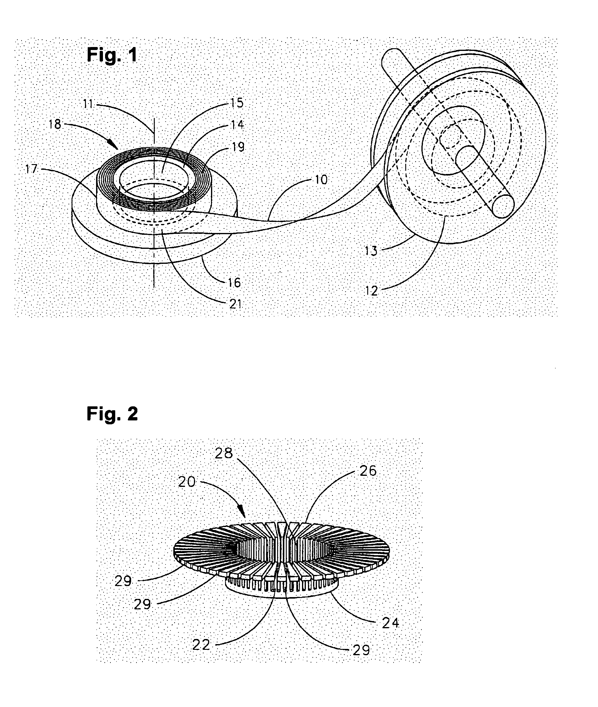
[0041] Referring to FIG. 1, there is depicted an embodiment of the invention, wherein soft magnetic metal ribbon 10 is wound about a winding axis 11 on an inner ring 14. Winding machine 13 includes supply roll 12 containing an indeterminate length of soft magnetic metal ribbon 10. Inner ring 14 is placed on winding plate 16. Soft magnetic metal ribbon 10 is spirally wound on inner ring 14, forming soft magnetic metal toroid 18 having a toroid axis. Soft magnetic metal toroid 18 has inner side surface 15 and outer side surface 17, generally formed by the surfaces of the innermost and outermost ribbon layers. Toroid 18 also has a top 19, and a bottom 21, generally formed by the exposed and aligned edges of the ribbon layers.

[0042] The soft magnetic metal ribbon 10 can be wound using a variety of horizontal and vertical axis machines and methods. Preferably, a consistent, firm toroid to be used as a pre-form will have at least an 85% wind density compared to the inherent ribbon densit...


PUM

PropertyMeasurementUnit
frequencyaaaaaaaaaa
frequenciesaaaaaaaaaa
thicknessaaaaaaaaaa

Abstract

An electromagnetic component is formed from a pre-form comprising layers of soft magnetic metal ribbon. Adhesive is applied to permeate the pre-form and is then cured. The bonded pre-form is placed within a milling assembly that supports and constrains the ribbon layers during a milling operation used to process the pre-form into an electromagnetic component shape. Optionally, the shape is thermally processed. The resulting electromechanical component has attractive soft magnetic properties, including low core loss, that render it useful as a component in electric motors and generators and static inductive devices operable at high excitation frequencies.

Description

RELATED U.S. APPLICATION DATA [0001] This application is a continuation-in-part of co-pending U.S. patent application Ser. No. 10 / 876,034, filed Jun. 24, 2004 which, in turn, is a continuation of U.S. patent application Ser. No. 10 / 763,728, filed Jan. 23, 2004 which, in turn, is a continuation-in-part of U.S. patent application Ser. No. 10 / 458,944, filed Jun. 11, 2003. Each of application Ser. Nos. 10 / 876,034, 10 / 763,728, and 10 / 458,944 is incorporated herein in its entirety by reference thereto.BACKGROUND OF THE INVENTION [0002] 1. Field of the Invention [0003] The invention relates to an electromagnetic component; and more particularly, to an electromagnetic component appointed for use in a dynamoelectric machine or inductive device, and a method for the manufacture of such a component. [0004] 2. Description of the Prior Art [0005] Multi-pole rotating electromechanical or dynamoelectric machines, such as motors, generators, re-gen motors, alternators, brakes and magnetic bearings ...

Claims


Application Information

Patent Timeline
Patent Type & Authority Applications(United States)
IPC IPC(8): B23C3/00H01F41/02H02K1/02H02K15/02H02K41/00
CPCB23C3/00B23C3/30H01F3/04H01F41/0226H01R43/08H02K1/02Y10T29/49078H01F1/15333Y10T29/49071Y10T29/4902Y10T29/49002Y10T29/4906Y10T29/49073H02K15/026
Inventor BERWALD, THOMAS J.PAGE, KENDALL S.HIRZEL, ANDREW D.
Owner BERG & BERG ENTERPRISES
Why Eureka
Try Eureka