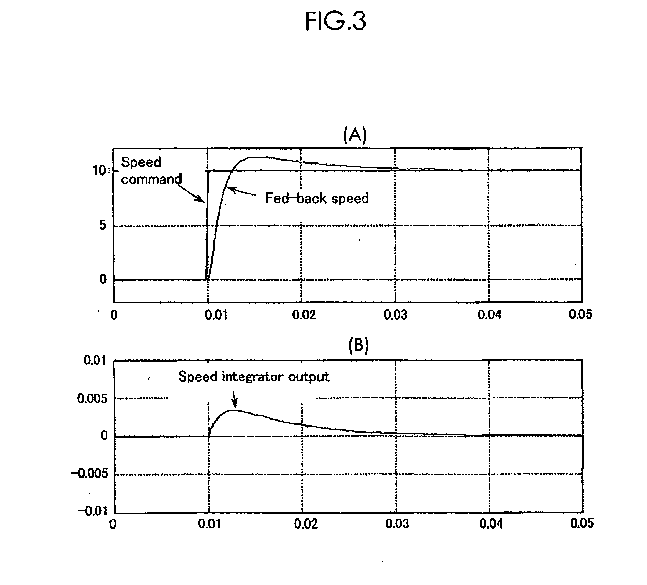
[0023] With the use of the speed integration compensation low-pass filter, in this invention, the difference between the speed indicated by the speed command with a
delay corresponding to the
delay of the
speed control system and the actually delayed fed-back speed can be rendered nearly zero. This makes the residual quantity in the speed
integrator almost zero, thus an overshoot of a fed-back speed can be reduced.
[0027] With the use of the delay compensation low-pass filter in the current control system, a current difference between a current indicated a current command with a delay corresponding to a delay of the current control system and an actually delayed fed-back current can be rendered nearly zero. Thus an overshoot can be decreased.
[0029] According to in this invention, a
feed forward multiplication output performs a proportional integral control in the
position control unit, so that the characteristics of a primary advance can be obtained. Thus a delay of the
speed control system can be compensated and the followability to a position command can be enhanced. With the use of a delay compensation low-pass filter in the speed control unit, a difference between a speed indicated by a speed command with a delay corresponding to a delay of the speed control system and an actually delayed fed-back speed can be rendered nearly zero. When the
feed forward gain is increased to 100%, a control system with less overshoots can be also constructed, which realizes to perform a
position control with the higher followability. Furthermore, the use of a
feed forward low-pass filter prevents ripples from being involved in the speed command itself. The ripples based on quantization errors are generated because of the presence of the position command unit.
[0032] By applying such a delay compensation low-pass filter in the
position control unit, a position command input into the position control unit, and a fed-back position
signal rise almost simultaneously when accelerating. Accordingly the speed command from the position control unit becomes considerably smaller. When the above mentioned construction is employed, the speed feed forward gain can be increased to 1 or close to 1, which improves the followability to the position command.
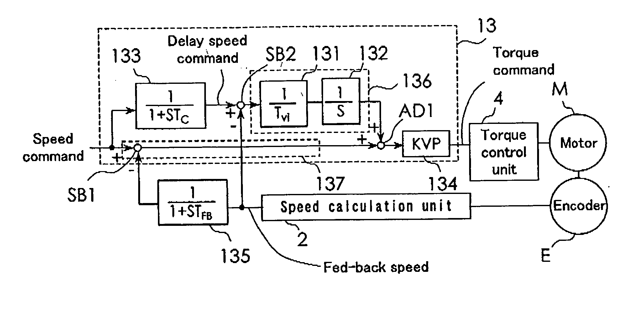
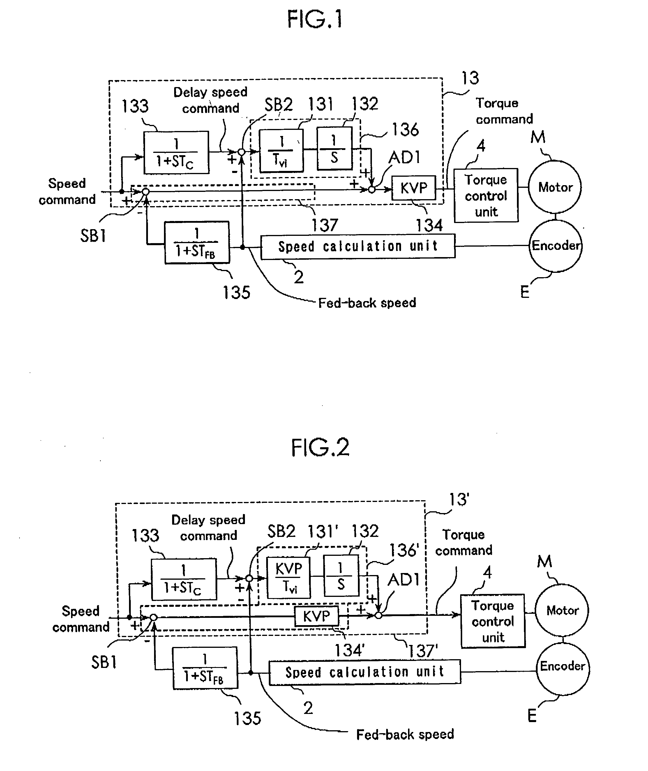
[0033] In this invention, the speed control unit comprises a delay compensation low-pass filter in the speed control unit in the speed control unit has a
transfer function corresponding to a delay of a speed control system. The integral control system includes a speed
integrator, which integrates a speed difference between a speed indicated by a delay speed command and the speed of the motor. The delay speed command is obtained by inputting the speed command into the delay compensation low-pass filter in the speed control unit. The
proportional control system outputs a command proportional to a difference between the speed indicated by the speed command and the speed of the motor. The addition means adds an output of the integral control system and an output of the proportional control system. The multiplication means multiplies an output of the addition means by a speed proportional gain to produce the torque command. In the proportional control system, the speed difference may be multiplied by the speed proportional gain and, in the integral control system, the
operand to be controlled may be multiplied by the speed proportional gain before being output. With the use of the delay compensation low-pass filter in the speed control unit as proposed in this invention, the difference between the speed indicated by the speed command with a delay corresponding to the delay of the speed control system and the actually delayed fed-back speed can be rendered nearly zero. This makes the residual quantity in the speed integrator almost zero, thus the followability to a position command can be improved.
[0035] The position control unit preferably comprises a subtraction means and a
position loop multiplication means. The subtraction means calculates a position difference between the position indicated by the position command and the position detected by the position detection unit. The
position loop multiplication means multiplies the position difference by the position proportional gain. In this case, it is preferred that the position control unit further includes a
differentiator for differentiating the position command, a multiplication means for multiplying the output of the
differentiator by the feed forward gain, and a feed forward low-pass filter having a
transfer function to eliminate ripples caused by quantization errors of the position command. The position control unit may also be constructed in such a manner that the feed forward low-pass filter can filter an added output of an output of the feed forward gain multiplication means and an output of the proportional differentiation means. The proportional differentiation means compensates a delay of the speed control system basing on a proportioned differentiation control which controls an output of the feed forward gain multiplication means multiplying an output of the differentiations by a feed forward gain.

