Micro electromechanical switch and method of manufacturing the same

a micro electromechanical switch and micro-electronic technology, applied in relays, door/window fittings, wing accessories, etc., can solve the problems of further miniaturization and counter-trends in the direction of lower voltage, and achieve the effect of increasing the displacement of the movable electrode by electrostatic attraction, reducing the applied voltage, and improving contact for

Inactive Publication Date: 2006-09-21
ORMON CORP
View PDF4 Cites 7 Cited by
  • Summary
  • Abstract
  • Description
  • Claims
  • Application Information

AI Technical Summary

Benefits of technology

[0033] The micro electromechanical switch according to the present invention, as described above, allows the amount of displacement of the movable electrode by electrostatic attraction to be increased by way of forming of the slit in the connecting part or lowering elastic constant of the connecting part. T

Problems solved by technology

Moreover, the methods B and C run counter to trends of techni

Method used


Image

  • Micro electromechanical switch and method of manufacturing the same
  • Micro electromechanical switch and method of manufacturing the same
  • Micro electromechanical switch and method of manufacturing the same

Examples


embodiment 1

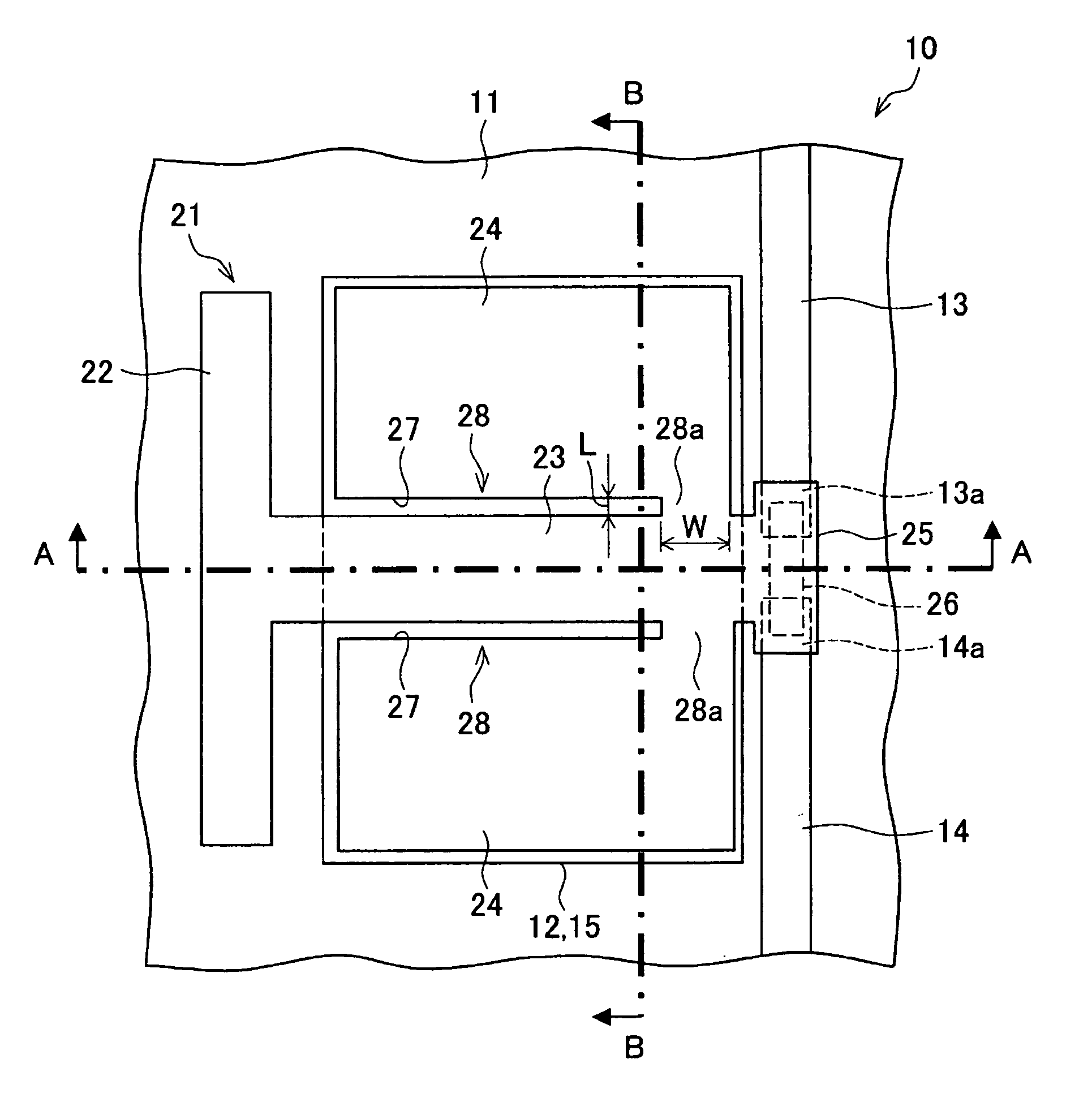
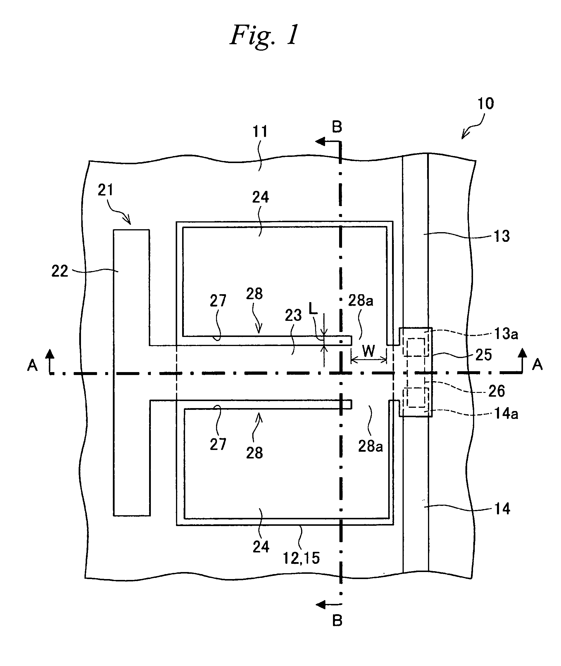
[0079] An exemplary embodiment of the present invention will be explained with reference to FIGS. 1-5. FIG. 1 shows schematically a micro electromechanical relay (micro electromechanical switch) according to the present embodiment. The micro electromechanical relay 10 comprises a base 11 and an actuator 21 that is partially affixed to an upper face of the base at a portion and separated from the base 11 at the other portion. An element that is the same is designated by the same reference. These figures may emphasize specific parts for understanding of the invention. Thus, the various of dimensions of the micro electromechanical relay 10 shown in these figures are not restricted to reflecting the various of dimensions of an actual micro electromechanical relay 10.

[0080] The base 11 is formed from a glass substrate such as Pyrex (Trademark). Upon the upper face of the base 11, a pair of signal lines 13 and 14 and a fixed electrode 12 are formed from a conductor such as gold, copper, ...

working example 1

[0101] A specific example of the micro electromechanical relay 10 of the present embodiment will be explained while referring to FIGS. 6-9. In this example, a longitudinal direction of the beam portion 23 is referred to as the lengthwise direction, and a narrow direction perpendicular to the lengthwise direction is referred to as the width direction. In the micro electromechanical relay 10 according to the present working example, the base 11 is formed from a glass substrate, and the fixed electrode 12 and the signal lines 13 and 14 are formed from Au. The actuator 21 is formed from a silicon semiconductor substrate, and the movable contact 26 is formed from Au.

[0102] In addition, the various dimensions of the micro electromechanical relay 10 are described below. Specifically, a length of the beam portion 23 is 450 μm, and a width is 120 μm. Further, the movable electrode 24 is 410 μm long and 500 μm wide. Furthermore, the contact part 28 has the same length (410 μm) as the movable...

embodiment 2

[0112] Another embodiment of the present invention will be explained with reference to FIG. 10. The micro electromechanical relay 10 according to the present embodiment differs from the micro electromechanical relay 10 shown in FIG. 1 in that a fixed electrode 12 is disposed on either side of the signal lines 13 and 14; and also the supporting portion 22, the beam portion 23, the movable electrode 24, and the connecting part 28 are disposed on either side of the movable contact portion 28; while the composition is similar otherwise. Elements having the same function as those explained for the above-mentioned embodiment are designated by the same references, and further explanation of such elements will be omitted.

[0113]FIG. 10 shows schematically the micro electromechanical relay 10 of the present embodiment. The illustrated actuator 21 supports the movable contact portion 25 from both sides and thus is called a “double-support type actuator.”

[0114] The micro electromechanical rela...


PUM


Abstract

A micro electromechanical relay opens and closes an electrical circuit by contact/separation between a fixed contact disposed on a base and a movable contact disposed on an actuator by driving of a movable electrode by electrostatic attraction by application of voltage between a fixed electrode disposed on the base and a movable electrode of the actuator. The actuator comprises a supporting portion disposed on the base, a beam portion extending in a cantilevered manner from the supporting portion, and a movable electrode and a movable contact elastically supported by the beam portion. The beam portion elastically supports, in order from the supporting portion end, the movable electrode and the movable contact. A slit is formed from the side of the supporting portion in the portion of the actuator connecting the beam portion and the movable electrode.

Description

BACKGROUND OF INVENTION [0001] 1. Field of the Invention [0002] The present invention relates to a micro electromechanical switch for opening and closing an electronic circuit by causing contact or separation between contacts using electrostatic attraction, a method for manufacture of such, and a device utilizing the micro electromechanical switch. In particular, the present invention relates to a structure of an actuator of a micro electromechanical switch. [0003] 2. Background Art [0004] A conventional micro electromechanical relay, which is one type of a micro electromechanical switch, will be explained with reference to FIGS. 40-45. FIG. 40 shows schematically the conventional micro electromechanical relay. The micro electromechanical relay 100 comprises a base 101 and an actuator 111 having a portion thereof fixed to an upper face of the base 101 and also having the other portion separated from the base 101. Furthermore, within these figures, an element that is the same is desi...

Claims


Application Information

Patent Timeline
IPC IPC(8): H01H51/22
CPCH01H1/0036H01H59/0009H01H2001/0084H01H2001/0089H01H2059/0081E05C3/167E05F11/10E05Y2900/132
Inventor MASUDA, TAKAHIROSEKI, TOMONORI
Owner ORMON CORP
Why Eureka
Try Eureka