
Node device for transfering supervisory control information in photonic network

a photonic network and node device technology, applied in data switching networks, wavelength-division multiplex systems, multiplex communication, etc., can solve the problems of limited transmission rate of supervisory control information, difficult to update the supervisory control information in the node device, and the conventional method of transferring supervisory control information

Inactive Publication Date: 2006-09-21
FUJITSU LTD
View PDF6 Cites 15 Cited by
  • Summary
  • Abstract
  • Description
  • Claims
  • Application Information

AI Technical Summary

Benefits of technology

[0030] A first object of the present invention is to transfer a large amount of supervisory control information while confirming the correspondence between each wave length path and supervisory control information, in a photonic network conducting path switching of the signal light.
[0031] A second object of the present invention is to update the supervisory control information while confirming the correspondence between each wavelength path and the supervisory control information, in a node device through which each wave length path is transmitted.
[0032] The node device according to the present invention comprises a plurality of input ports and a plurality of output ports in which signal light which is input from one of the above input ports is output from one of the above output ports. This node device comprises a reception device, an extr

Problems solved by technology

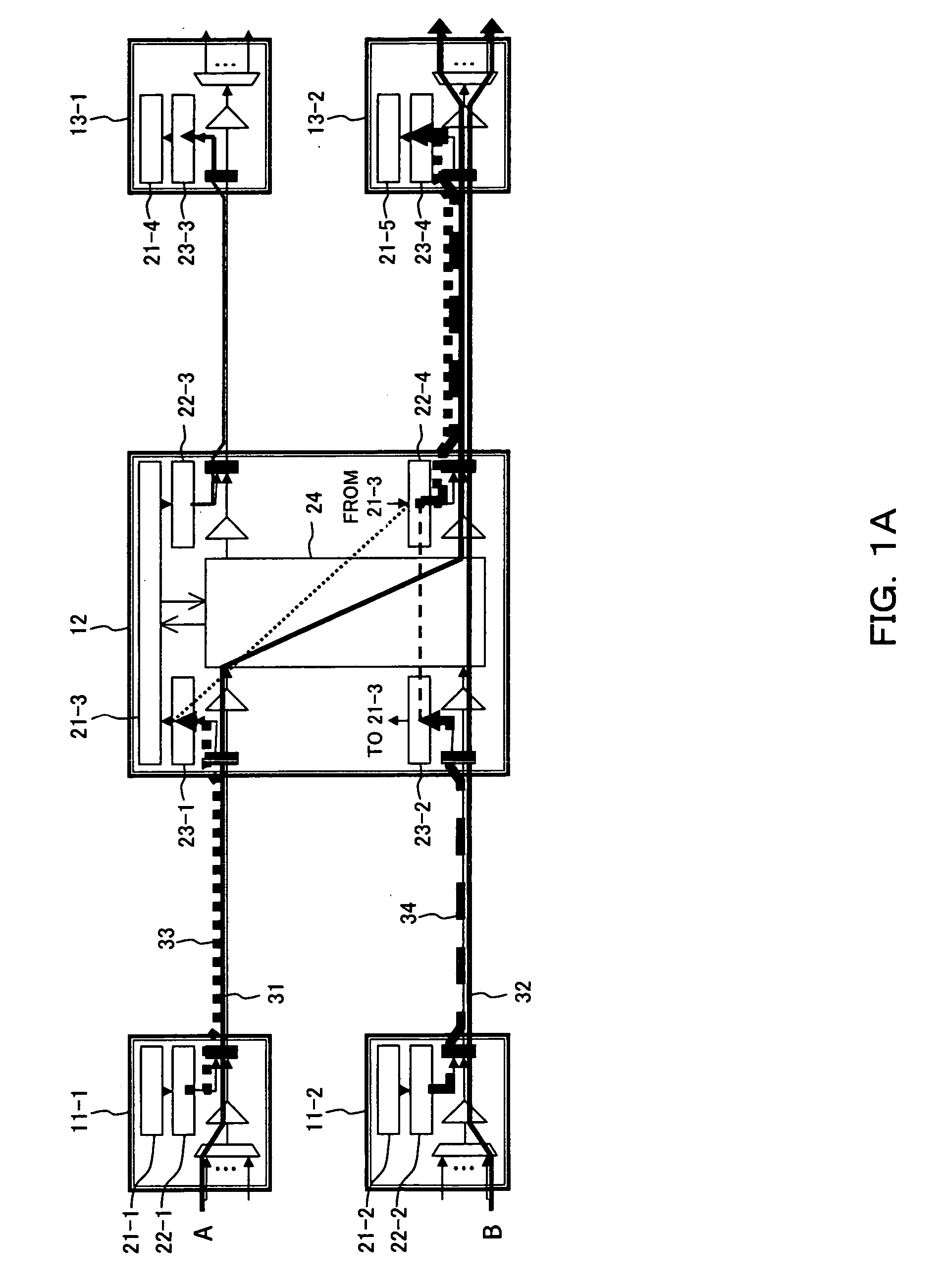
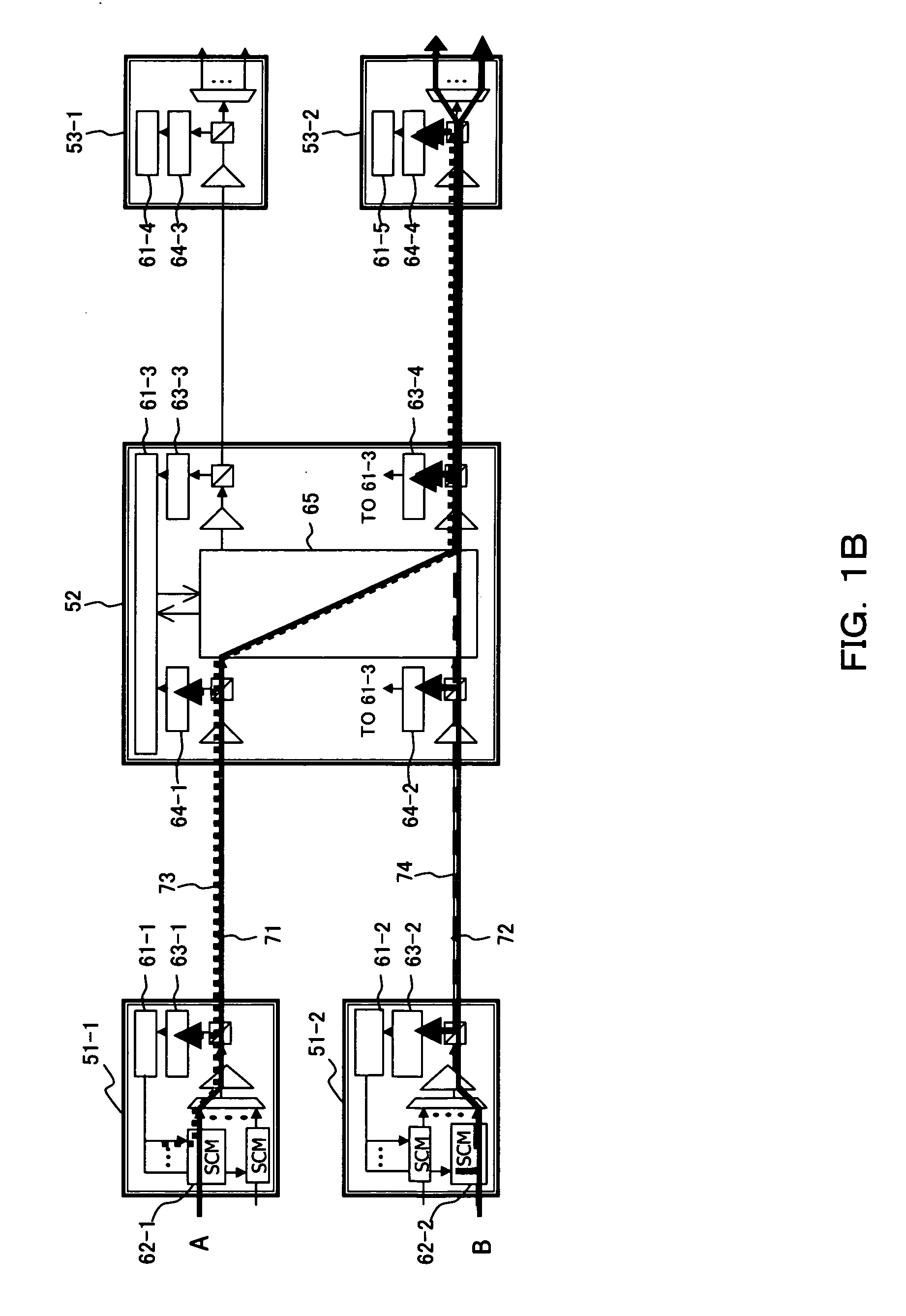
The above conventional method of transferring supervisory control information has problems as below.
Accordingly, the transmission rate of the supervisory control information is limited.
Also, in many cases in the main signal superposition method, the supervisory control information can be generated only by the transmission terminal station in each wavelength path and it is difficult to update the supervisory control information in the node devices through which each wavelength path is transmitted as shown in FIG. 1B.
Therefore, the main signal superposition method is not suitable for transferring the supervisory control information which has to be updated along the route of the wavelength path.

Method used


Image

  • Node device for transfering supervisory control information in photonic network
  • Node device for transfering supervisory control information in photonic network
  • Node device for transfering supervisory control information in photonic network

Examples


Embodiment Construction

[0048] Hereinafter, the most preferred embodiments of the present invention will be explained in detail, by referring to the drawings.

[0049]FIG. 2 shows a principle of a node device of the present invention. The node device in FIG. 2 comprises a plurality of input ports and a plurality of output ports, and signal light which has been input from one of the above input ports is output from one of the above output ports. The node device comprises a reception device 101, an extraction device 102, a control device 103 and a transmission device 104.

[0050] The reception device 101 receives supervisory control information on a dedicated wavelength being different from the wavelength of the signal light, which is input together with the signal light from an input port 111. The extraction device 102 extracts information superposed on the optical main signal of the signal light which is to be output from an output port 112. A control device 103 confirms whether or not the signal light to be ...


PUM


Abstract

A node device receives supervisory control information on a dedicated wavelength different from a wavelength of signal light, which is input from an input port together with the signal light, and extracts, from signal light to be output from an output port, information superposed on an optical main signal of the signal light. Then, it is confirmed whether or not the signal light to be output and the supervisory control information correspond by using the extracted information, and supervisory control information corresponding to the signal light to be output is transmitted on the dedicated wavelength from the output port.

Description

BACKGROUND OF THE INVENTION [0001] 1. Field of the Invention [0002] The present invention relates to a node device for transferring supervisory control information in a photonic network having various network topology configurations such as ring interconnection, mesh connection or the like for accommodating and transmitting signals for various services. [0003] 2. Description of the Related Art [0004] Conventionally, a network topology configuration in the photonic network system has employed a point-to-point configuration. However in recent years, the construction of the photonic network systems employing the ring topology and the mesh topology are studied in which the OADM (Optical Add / Drop Multiplexing) node and the HUB node for realizing the path switching of the signal as the light without the photoelectric conversion are used. [0005] Also, the OTN (Optical Transport Network), the Ethernet (registered trademark), the FC (Fiber Channel) and the like have been added to the types o...

Claims


Application Information

Patent Timeline
IPC IPC(8): H04L12/56H04B10/07H04B10/077H04B10/291H04J3/00H04J3/14H04J14/00H04J14/02
CPCH04B10/077H04L41/04H04L41/12H04L41/344
Inventor KATAGIRI, TORUNAITO, TAKAO
Owner FUJITSU LTD
Learn More