Method and system of structural light-based 3D depth imaging using signal separation coding and error correction thereof

a signal separation and depth imaging technology, applied in the field of 3d depth imaging method and system, can solve the problems of poor accuracy and robustness of the method, inability to rapidly change the scene, and affect the spatial coding by signal modification or complexity

Inactive Publication Date: 2006-09-21
ING GROUP NV
View PDF3 Cites 66 Cited by
  • Summary
  • Abstract
  • Description
  • Claims
  • Application Information

AI Technical Summary

Benefits of technology

[0016] The present invention also provides a signal separating and coding method and system for correspondence point determination capable of exactly separating a signal even when the signal is distorted by a complex boundary surface of an object in 3D depth imaging.
[0017] The present invention also provides a signal separating and codin...

Problems solved by technology

However, the accuracy and robustness of the method are poor due to ambient illumination variation and noise.
However, spatial coding is affected by signal modification or complexity of an object because it uses spatially arranged address information for pixel correspondence.
However, temporal coding is not suitable for a rapidly changing scene because of its use of a frame sequence.
However, hybrid coding cannot be used in a very complex environment because it has the shortcomings ...

Method used


Image

  • Method and system of structural light-based 3D depth imaging using signal separation coding and error correction thereof
  • Method and system of structural light-based 3D depth imaging using signal separation coding and error correction thereof
  • Method and system of structural light-based 3D depth imaging using signal separation coding and error correction thereof

Examples


first embodiment

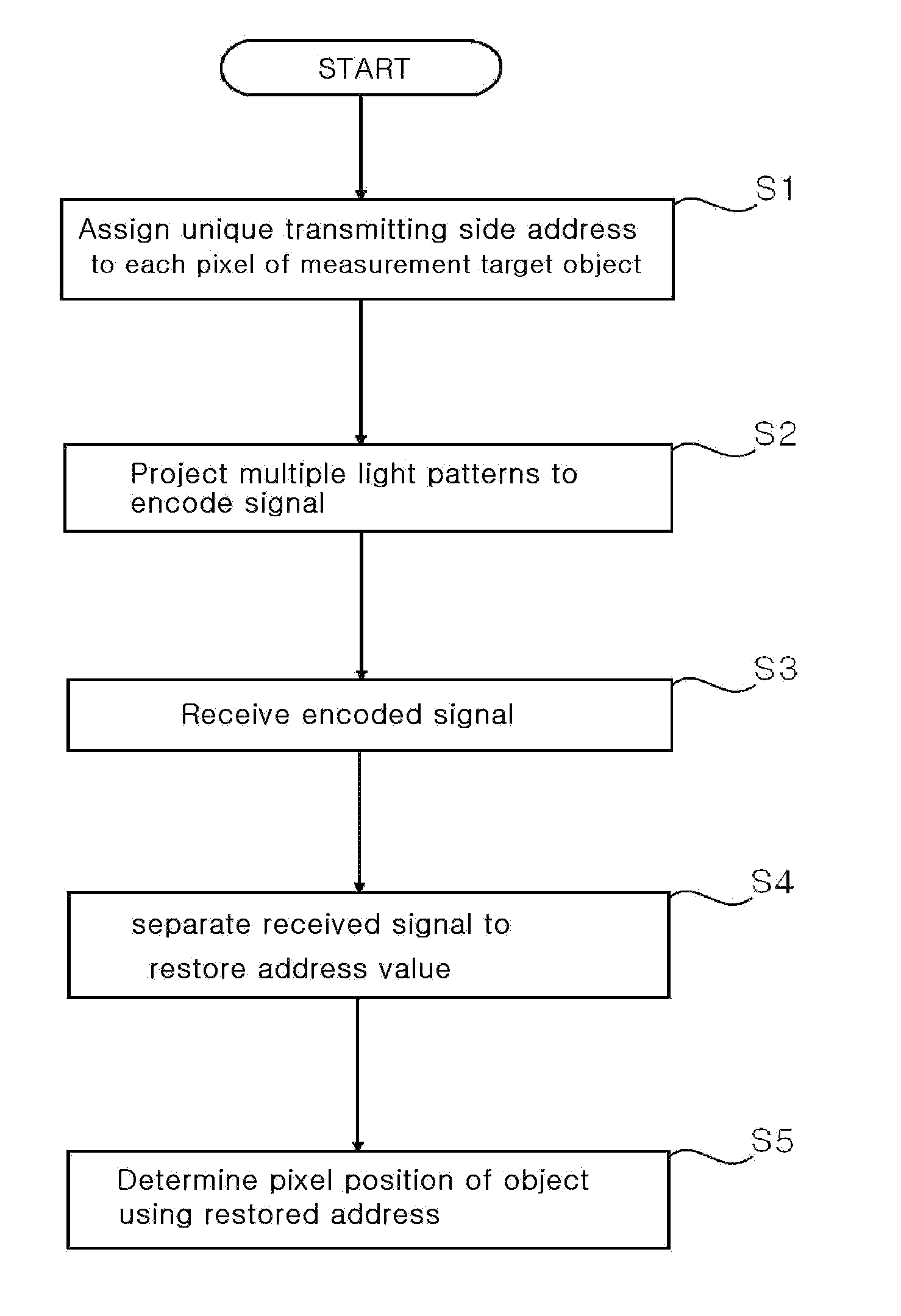
[0054]FIG. 3 is a flowchart illustrating a 3D imaging method using signal separation according to an embodiment of the present invention.

[0055] As shown in FIG. 3, a unique transmitting side address is assigned to a signal corresponding to each pixel of a measurement target object, in step S1. In step S2, multiple light patterns are projected by the projection means to encode a signal including the transmitting side address. Each pattern is received in step S3. In step S4, an original signal is separated through a signal separation process. A correspondence point is calculated from the restored signal in step S5.

[0056] The steps are performed by a processing means that processes collected data. That is, the processing means used in the present invention is a processor that can perform steps S1 to S5. The processing means is typically implemented by a computer system.

[0057] An example of the signal encoding and decoding processes and the error detection and correction used in the ...

second embodiment

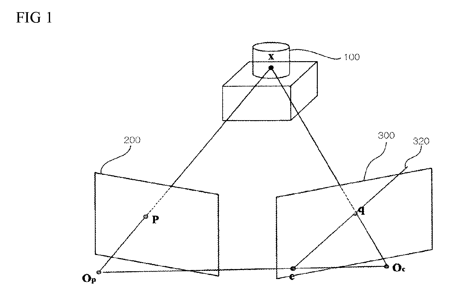
[0090] The signal separation coding scheme according to the first embodiment is to estimate signal mixture between the projector pixel and the camera pixel in order to determine the pixel correspondence. In the mixed-signal separation process, a result of projecting the received signal to a hierarchical orthogonal signal group is represented in a projector-camera signal space. 3D depth image calculation is a process of determining a projector side signal corresponding to each pixel of the camera in the projector-camera signal space.

[0091] The second embodiment suggests (1) a scheme for creating an image at a time point of a projector without explicit 3D restoration, (2) a new method for restoring 3D by simultaneously calculating a pixel-by-pixel correspondence between the created stereo image and the structural light, using Hermann von Helmholtz's complementarity principle that light from one light source reflected on an object surface can be equally interpreted as light from a rec...


PUM


Abstract

A 3D depth imaging method and system are disclosed. The 3D depth imaging method involves radiating light at a measurement target object using a projection means and imaging the light using an image receiving means, and includes the steps of assigning a unique transmitting side address to a signal corresponding to each pixel of the projection means to encode the signal; projecting multiple light patterns at the projection means to transmit the signal; receiving the encoded signal at the image receiving means; separating the received signal to restore the address; and determining a pixel position of the object using the transmitting side address and the restored address. With the 3D depth imaging method and system, it is possible to exactly separate signals received by the image receiving means even when the signals are overlap and the geometrical structure of the object varies, and it is also possible to obtain a depth image that is robust against ambient environmental noise.

Description

BACKGROUND OF THE INVENTION [0001] 1. Field of the invention [0002] The present invention relates to a 3D depth imaging method and system, and more particularly, to a 3D depth imaging method and system capable of more exactly imaging a 3D depth by exactly restoring a modified signal using a new scheme called signal separation coding. [0003] 2. Description of the Prior Art [0004] In general, a method of three-dimensional (3D) depth imaging using a structural light is recently receiving attention because it is suitable for sensing a 3D environment in service robotics. The basic principle of depth imaging using a structural light, which is an active stereo scheme, is to radiate light at an object using a projection means such as a projector, image the object irradiated with light using an image receiving means such as a camera, and observe the extent of distortion of the light due to the object in order to calculate the depth of the object and obtain a depth image. [0005]FIG. 1 is a sc...

Claims


Application Information

Patent Timeline
IPC IPC(8): G06K9/00G06V10/145
CPCG01B11/2513G06K9/2036G06T7/0057G06T7/521G06V10/145
Inventor LEE, SUK-HANCHOI, JONG-MOOKIM, DAE-SIKOH, SEUNG-SUB
Owner ING GROUP NV
Why Eureka
Try Eureka