Fuel cell

a fuel cell and stack technology, applied in the field of fuel cells, can solve the problems of low productivity time-consuming, complicated assembling operation of the fuel cell stack, etc., and achieve the effects of improving productivity, convenient assembling operation, and economic and compact structur

Inactive Publication Date: 2006-09-21
HONDA MOTOR CO LTD
View PDF4 Cites 26 Cited by
  • Summary
  • Abstract
  • Description
  • Claims
  • Application Information

AI Technical Summary

Benefits of technology

[0012] A main object of the present invention is to provide a fuel cell with a plurality of unit cells having economical and compact structure in which it is possible to achieve easy, rapid assembling operation, improved productivity, and desired performance.
[0019] In the present invention, the anodes and the cathodes are formed on both surfaces of the elongated electrolyte membrane. Thus, by folding the elongated electrolyte membrane in a wave shape, it is possible to arrange the anodes and the cathodes in the desired orientation. In the structure, simply by inserting the gas diffusion current collector members each having the substantially U-shape from both sides of the elongated electrolyte membrane, in effect, a plurality of unit cells can be stacked together easily and rapidly. Each of the unit cells includes the membrane electrode assembly unit and gas diffusion current collector members sandwiching the membrane electrode assembly unit, and the membrane electrode assembly unit includes the anode, the cathode, and the electrolyte membrane interposed therebetween.
[0020] Further, each of the gas diffusion current collector members is formed by folding the single electrically conductive plate in the substantially U-shape. Thus, electrons flow from the anode to the cathode through the electrically conductive plate itself, and it is possible to effectively reduce the electrical resistance. Further, simply by supplying the coolant along the folded positions of the electrically conductive plate, the metal thermal conductivity is utilized to achieve the uniform temperature in the surfaces of the gas diffusion current collector members.

Problems solved by technology

Consequently, the assembling operation of the fuel cell stack is significantly complicated, and time consuming.
Thus, productivity for the fuel cell stack is low.

Method used


Image

  • Fuel cell
  • Fuel cell
  • Fuel cell

Examples


Embodiment Construction

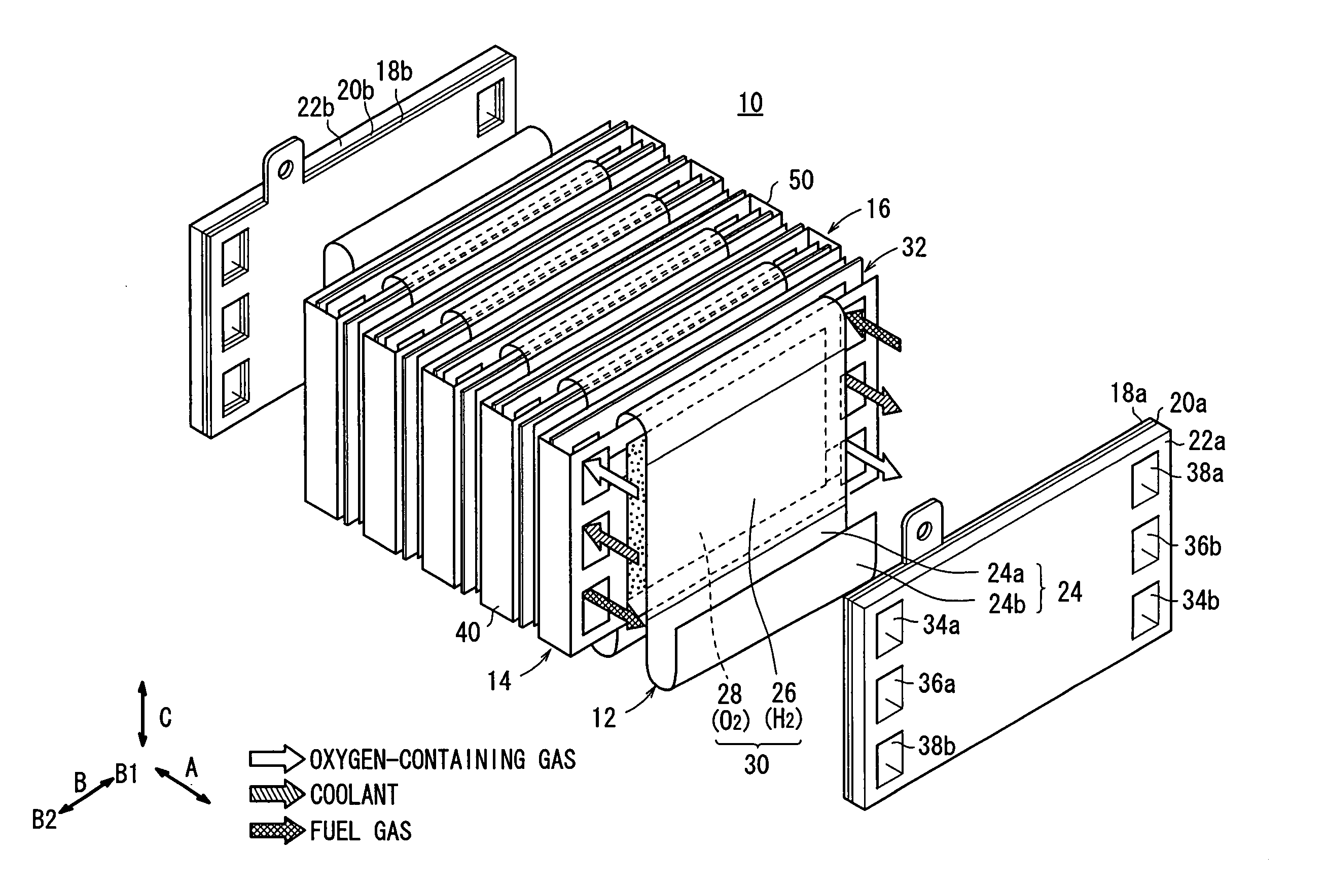
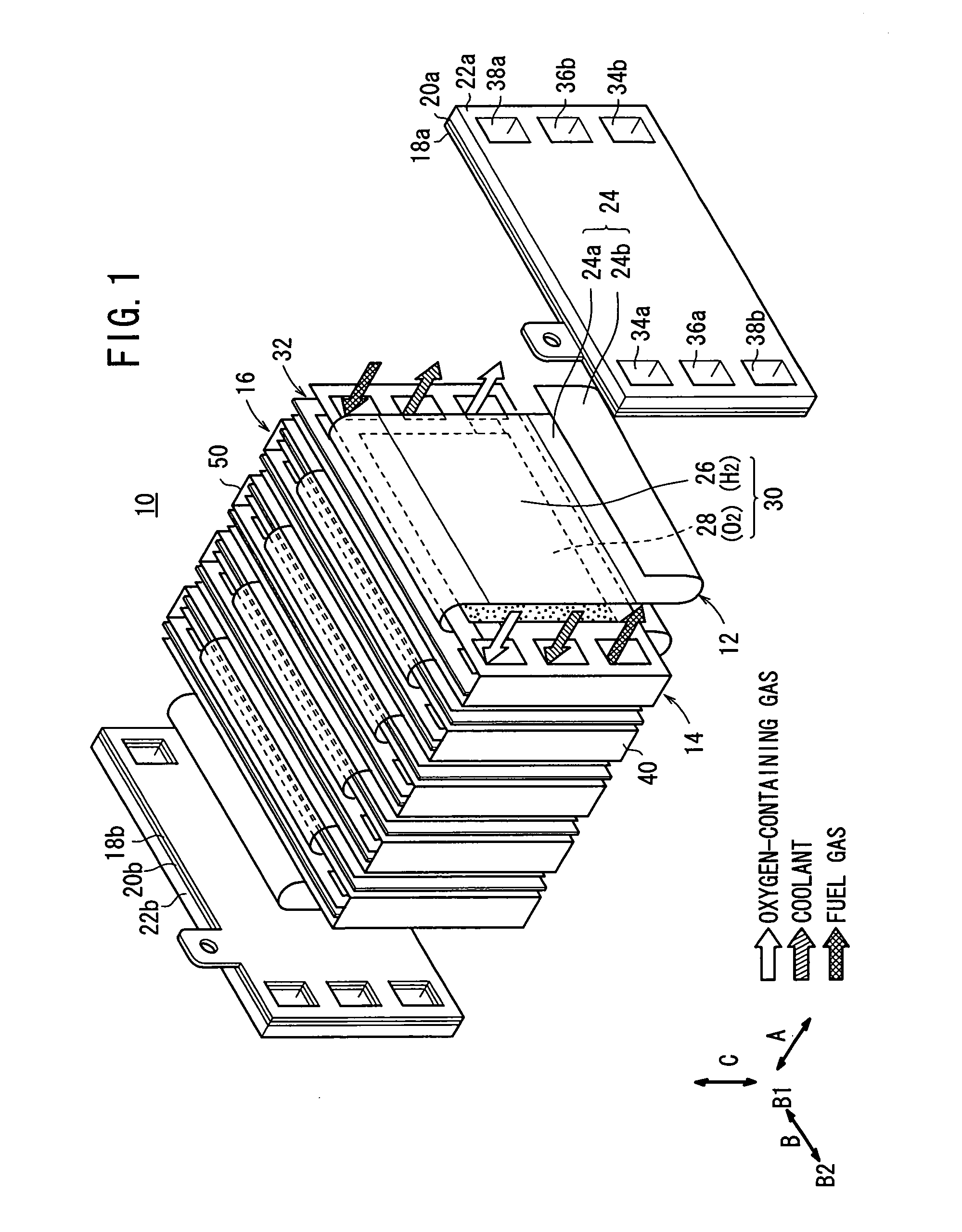
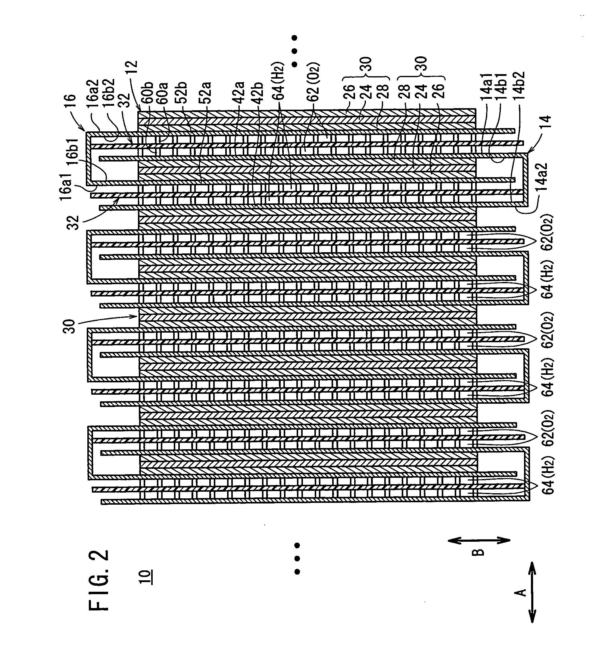
[0031]FIG. 1 is a view schematically showing structure of a fuel cell 10 according to an embodiment of the present invention. FIG. 2 is a cross sectional view showing the fuel cell 10.

[0032] For example, the fuel cell 10 is mounted on a vehicle such as an automobile. The fuel cell 10 has multi-layer structure like a fuel cell stack. The fuel cell 10 includes an electrolyte membrane / electrode web member 12, and first and second gas diffusion current collector members 14, 16 each having a substantially U-shape. The first and second gas diffusion current collector members 14, 16 facing each other are inserted into the electrolyte membrane / electrode web member 12 from both sides of the electrolyte membrane / electrode web member 12 in directions indicated by arrows B1 and B2. Thus, a plurality of layers of the first and second gas diffusion current collector members 14, 16 are stacked together in a direction indicated by an arrow A.

[0033] As shown in FIG. 1, at opposite ends of the fuel...


PUM

PropertyMeasurementUnit
electrically conductiveaaaaaaaaaa
shapeaaaaaaaaaa
chemicalaaaaaaaaaa

Abstract

An electrolyte membrane / electrode web member includes an elongated solid polymer electrolyte membrane. A plurality of anodes and a plurality of cathodes are provided on one surface, and on the other surface of the solid polymer electrolyte membrane, respectively. First and second gas diffusion current collector members are inserted into the electrolyte membrane / electrode web member from both sides. Each of the first and second gas diffusion current collector members is formed by folding a single electrically conductive plate into a substantially U-shape. Electrical insulation is provided by interposing the insulating member between the first and second gas diffusion current collector members.

Description

BACKGROUND OF THE INVENTION [0001] 1. Field of the Invention [0002] The present invention relates to a fuel cell including a plurality of unit cells, formed by sandwiching an elongated electrolyte membrane / electrode web member by gas diffusion current collector members. A plurality of anodes and cathodes are provided on both surfaces of the electrolyte membrane / electrode web member. [0003] 2. Description of the Related Art [0004] For example, a polymer electrolyte fuel cell employs a membrane electrode assembly (MEA) which includes an anode, a cathode, and an electrolyte membrane interposed between the anode and the cathode. The electrolyte membrane is a solid polymer ion exchange membrane. The membrane electrode assembly and separators sandwiching the membrane electrode assembly make up a unit of a power generation cell for generating electricity. Normally, a predetermined number of the power generation cells are stacked together to form a fuel cell stack. [0005] In the fuel cell, ...

Claims


Application Information

Patent Timeline
Patent Type & Authority Applications(United States)
IPC IPC(8): H01M4/94H01M8/10H01M8/02
CPCH01M8/0254H01M8/1004H01M8/241H01M2008/1095Y02E60/521H01M8/0267H01M8/2457H01M8/2483Y02E60/50H01M8/242
Inventor INOUE, MASAJIRO
Owner HONDA MOTOR CO LTD
Why Eureka
Try Eureka