Controlled release mechanism for balloon catheters

a balloon catheter and controlled release technology, applied in the field of balloon catheters, can solve the problems of affecting the safety of patients, and difficulty in removing the balloon from the body conduit, so as to prevent catastrophic balloon rupture, reduce pressure, and prevent the occurrence of vessel dissection or rupture.

Active Publication Date: 2006-09-21
WL GORE & ASSOC INC
View PDF13 Cites 15 Cited by
  • Summary
  • Abstract
  • Description
  • Claims
  • Application Information

AI Technical Summary

Benefits of technology

[0009] Another object of the present invention is to provide a controlled pressure release catheter with a retainer provided at the end of the catheter shaft spaced apart from the securing band to prevent loss of the securing band in the event of a balloon failure. The device comprises a catheter shaft and inflatable balloon mounted on the catheter shaft via at least one securing band. A retainer is spaced apart from the securing band. In the event of over-pressurization, the retainer has an outer dimension which is greater than or equal to that of the inner dimension of the securing band to impede axial movement and prevent the securing band from breaking free of the catheter device even at excessive pressures.
[0010] Another object of the present invention is to provide a controlled pressure release balloon catheter which withstands high inflation pressures and prevents catastrophic balloon rupture due to over-pressurization. The device has an angled-cut tail on the balloon attached via a securing band to a catheter shaft with varying outer dimensions. A retainer is further provided at the distal end of the catheter shaft spaced apart from and distal to the securing band to prevent loss of the securing band in the event of a balloon failure.
[0011] Another object of present invention is to provide a controlled axial pressure release catheter wherein the balloon is predictably and safely prevented from material ruptures and fragmentation during over-pressurization by allowing controlled axial pressure release. The substantially axial release of inflation media which occurs upon over-inflation of the balloon in a catheter results in a release of inflation media in a non-perpendicular manner as related to the vessel wall. The pressure release mechanism is not directly opposed to the vessel wall thereby avoiding direct contact with the vessel wall. The benefit of substantial axial release of the inflation media is that the pressure exerted by the inflation media upon exit from the balloon is substantially reduced prior to contact with the vessel wall. This reduced pressure may prevent the occurrence of vessel dissection or rupture. In one embodiment of the present invention the inflation medium is released in a longitudinal direction substantially parallel to the longitudinal axis of the catheter shaft.

Problems solved by technology

In use, catheter balloons are known to occasionally rupture due to inflation to higher than designed for pressures.
Sudden rupture and corresponding sudden radial release of inflation pressure fluids or gases has resulted in injury to patients.
During a rupture, even if the balloon remains intact, the configuration of the damaged balloon may make withdrawal of the balloon from the body conduit quite difficult.
These occasional ruptures can also result in portions of the balloon or emboli being dispersed into the blood vessel or conduit of the patient.
Due to displacement of the fragments distally as a result of fluid flow through the blood vessel or conduit, retrieval is difficult and may require interventional surgery.
It is further difficult to ascertain with certainty that all pieces have been retrieved.
A sudden rupture and release of inflation media due to over-pressurization may also result in damage to the vessel wall requiring additional surgery.
None of the prior art balloon catheters provide catheter balloon seals having reliable and controlled failure mechanisms for the prevention of catastrophic failure of the balloon material during overpressure conditions.

Method used


Image

  • Controlled release mechanism for balloon catheters
  • Controlled release mechanism for balloon catheters
  • Controlled release mechanism for balloon catheters

Examples


Embodiment Construction

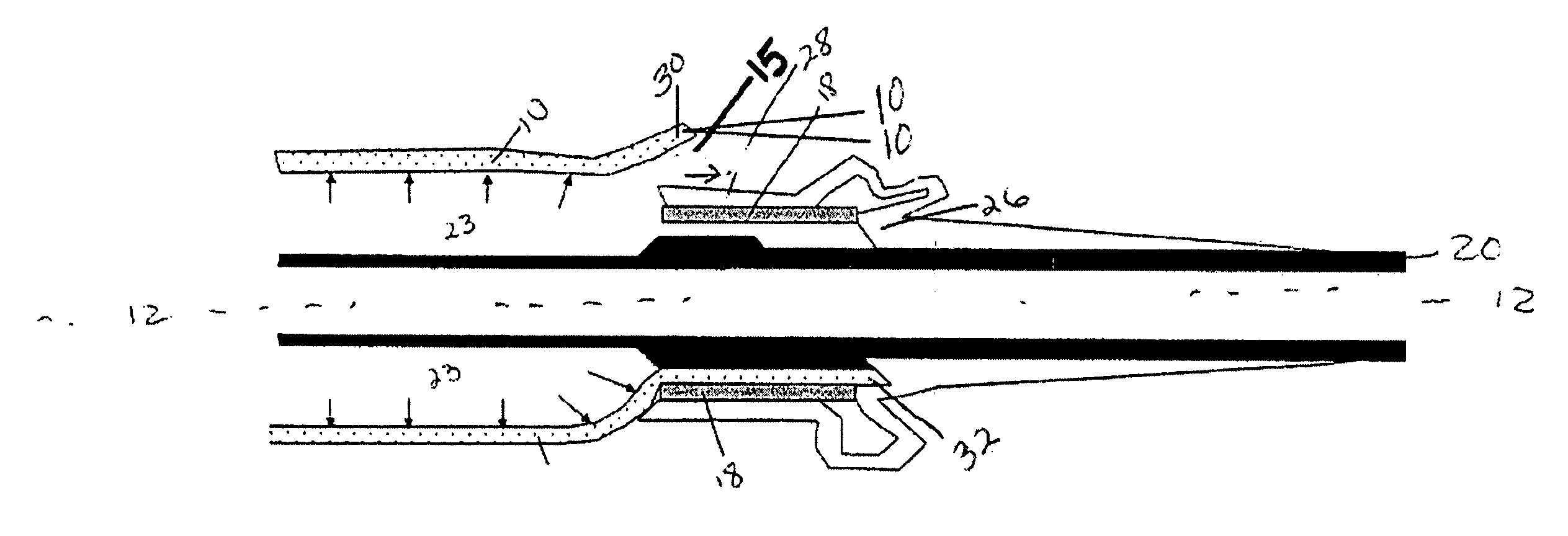
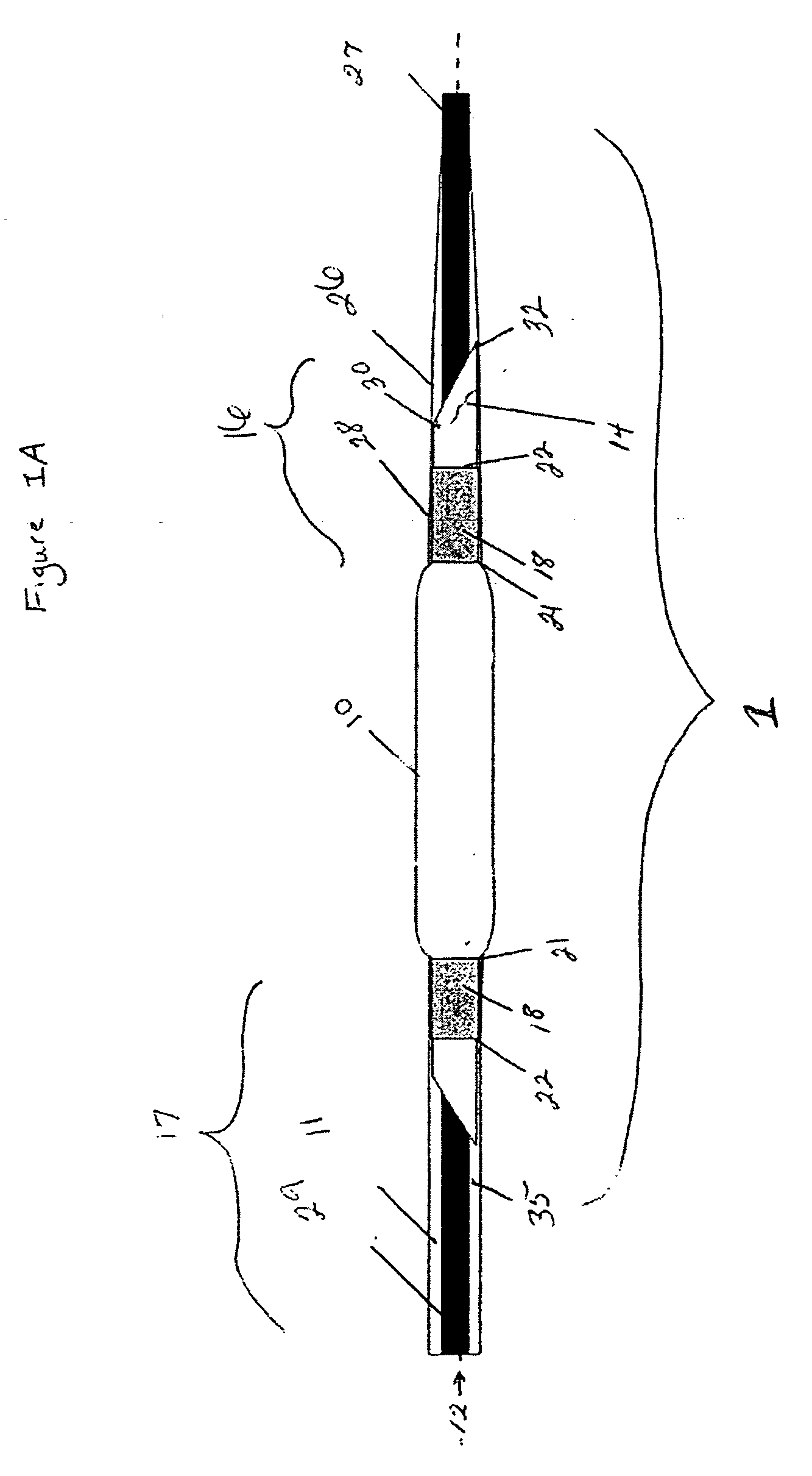
[0022]FIG. 1A is a schematic view of a non-inflated controlled pressure release balloon catheter device of the present invention having a controlled failure mechanism in the form of an angled-cut tail present on the balloon. The controlled pressure release catheter device comprises at least a catheter shaft, an inflatable balloon (hereinafter referred to as balloon) with an angled-cut tail, and at least one securing band. The catheter shaft has a longitudinal axis 12 extending between a proximal end 29 and a distal end 27 of the catheter shaft. The balloon has two ends wherein at least one end of the balloon comprises an angled-cut tail. For the purposes of the present invention, the ends of the balloon are those end portions of the balloon that are affixed to a shaft via a securing band 18 and any other portion of the balloon that is on the opposite side of the securing band from the center of balloon 10. The distal end of the balloon 16 is shown mounted or located at the distal en...


PUM


Abstract

This invention relates to the field of balloon catheters and more particularly to catheter balloons having controlled failure mechanisms for the prevention of catastrophic failure of the balloon during overpressure conditions.

Description

FIELD OF THE INVENTION [0001] The present invention relates to the field of balloon catheters and more particularly to catheter balloons having controlled failure mechanisms for the prevention of catastrophic failure of the balloon during overpressure conditions. BACKGROUND OF THE INVENTION [0002] Balloon catheters are used for a variety of medical procedures, including endovascular treatments. These endovascular treatments are carried out in the lumen of a vascular duct or vessel and have the advantage of being less aggressive and invasive than open surgery. Their conventional use entails the insertion of the balloon catheter into a body conduit at an entrance site and pushing the length of the catheter progressively into the body conduit until the balloon located at the distal end of the balloon catheter reaches the desired site. The balloon is then inflated at that site in order to implement the desired therapy. The body conduit is most often a blood vessel and more particularly ...

Claims


Application Information

Patent Timeline
Patent Type & Authority Applications(United States)
IPC IPC(8): A61M29/00A61F2/958
CPCA61M25/1018A61M2025/1093A61M25/10184A61M25/1011A61M2025/1015
Inventor DAVIDSON, JAMES F.DOYLE, MATTHEW E.GIOVALE, PETER R.KING, DAVID R.KRONCKE, PAUL M.PEARSALL, ALISON KEACH
Owner WL GORE & ASSOC INC
Why Eureka
Try Eureka