Arthroscopic shaver and method of manufacturing same

a shaver blade and blade technology, applied in the field of shaver blades, can solve the problems of inability to grind the inner cutting edge, inconvenient tearing, inefficient geometry for cutting tissue, etc., and achieve the effect of improving efficiency

Inactive Publication Date: 2006-09-21
ARTHREX
View PDF18 Cites 68 Cited by
  • Summary
  • Abstract
  • Description
  • Claims
  • Application Information

AI Technical Summary

Benefits of technology

[0021] Accordingly, it is an object of the present invention to produce an arthroscopic shaver with improved efficiency when cutting bone.
[0022] It is also an object of the present invention to produce an arthroscopic shaver which cuts bone efficiently regardless of the portion of the cutting edge in contact with the bone.
[0023] It is also an object of the present invention to produce an arthroscopic shaver which efficiently cuts bone and soft tissue.

Problems solved by technology

The edges formed have large included angles, geometry inefficient for cutting tissue.
Such tearing is undesirable since the torn tissue may frequently become wrapped into the gap between the inner and outer tubes so as to prevent the tissue from aspirating from the site thereby clogging the instrument.
Conversely, it is only possible to grind inner cutting edges with large included-angles.
These ground edges may have teeth of various sizes and shapes, but little other geometries are possible.
Advanced geometry outer cutting edges have little effect on the efficiency of a shaver when cutting bone.
This higher pressure causes localized “failure” in the log thereby allowing the cutting edge to penetrate the log.
All will cause localized failure in the bone which they encounter and will penetrate the bone.
During propagation, the cutting edge advances further into the bone with spreading of the bone by the cutting edges causing a tensile failure in the material ahead of the edge.
In the distal radius, however, the geometry is not well suited to bone cutting.
However, when the angle between the axis and the bone surface is high, so that the distal radius of the shaver is brought into contact with bone, the high included angle portion of the edge does not penetrate the bone and causes the shaver to bounce away from the bone.
The edges produced are irregular and have rough surface finishes on the surfaces over which tissue must slide during the cutting process and this limits the efficiency of the shavers.
Insufficient yield strength of the cutting edge material results in plastic deformation of the cutting edges.
This “mushrooming,” in turn, results in dulling of the cutting edge and the generation of metallic debris as the deformed inner cutting edges interfere with the outer cutting edges and as the deformed metal causes galling of the inner surface of the outer tube in the region of the cutting window.
These alloys generally have low yield strengths, not well suited to cutting edges for resection of bone.
However, these 300 series stainless materials generally have low yield strengths, particularly in shavers in which the inner tube is formed from a single piece of tubing.
Shavers made with 300 series inner cutting edges are not well suited to resection of bone since the edges undergo plastic deformation, unless the included angle of the cutting edges is increased to decrease the compressive stress at the edge.
Producing such cutting edges, however, is problematic since, as noted previously, the geometry of inner cutting edges does not allow their manufacture by grinding.
This recast material is extremely brittle due to its rapid solidification rates, has cracks in it, and has portions which may be only loosely bonded to the surface of the partpiece.
The EDM process is poorly suited to the manufacture of cutting edges, particularly those for use on tissue.
Milling is able to produce channels like those used in the prior art shavers currently available, however, the small size of the channels makes the milling of these channels problematic.
An end-mill of this diameter is extremely fragile and requires high rotational speeds and low feed rates, both for preservation of the end-mill and to prevent the end-mill from flexing (wandering) and making products with a high degree of dimensional variability.
Producing such a channel by milling with an end-mill is not economically feasible.
Endmills of these small diameters are prone to breakage and also flexing during use resulting in dimensional variation in the finished parts.
The endmills dull quite rapidly during use, further exacerbating the breakage and flexure problems.
EDM, however, produces rough surface finishes and irregular cutting edges.
Also, the electrodes used to produce the EDMed windows erode during use and must be periodically refurbished.

Method used


Image

  • Arthroscopic shaver and method of manufacturing same
  • Arthroscopic shaver and method of manufacturing same
  • Arthroscopic shaver and method of manufacturing same

Examples


Embodiment Construction

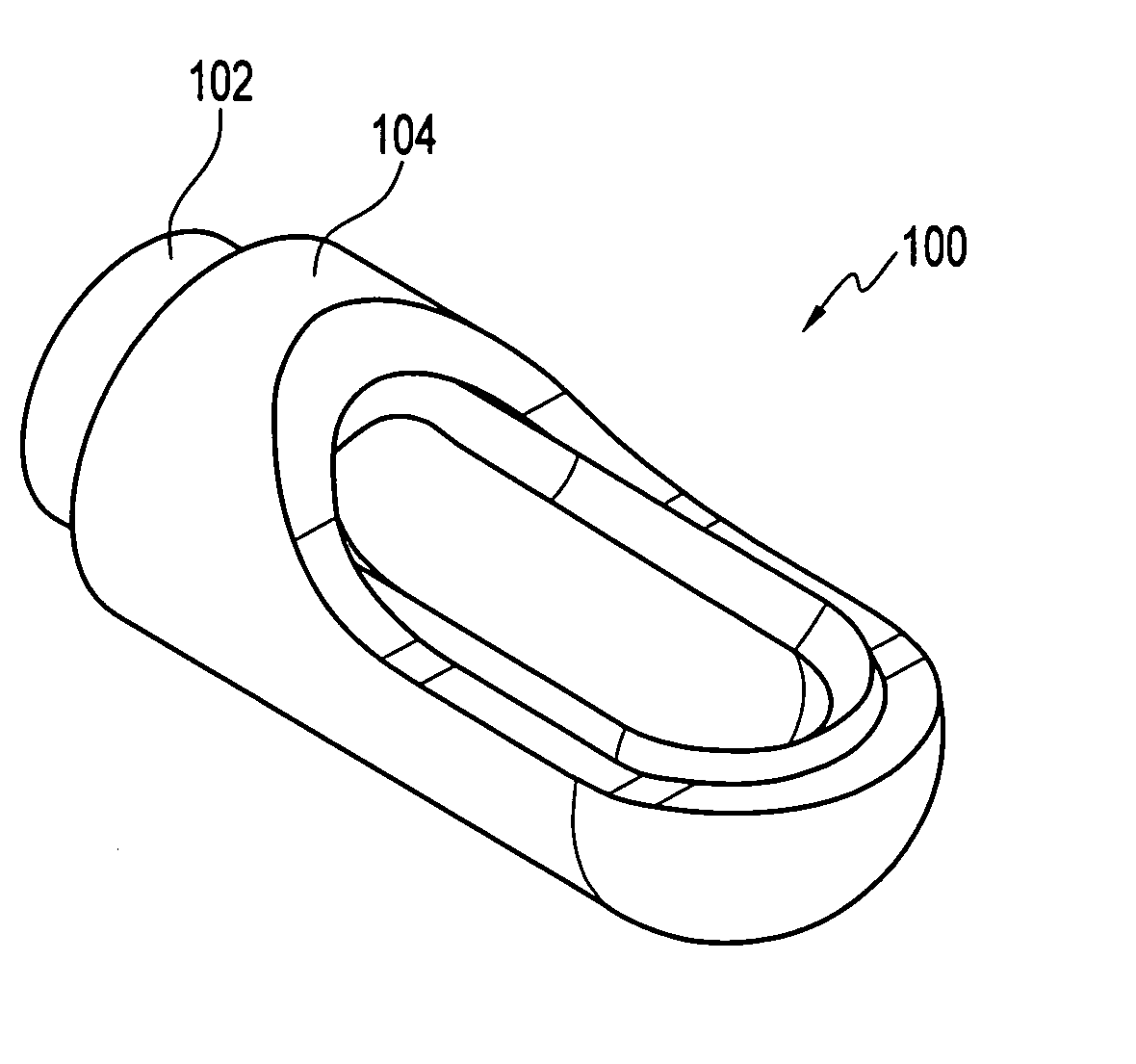
[0079]FIGS. 8 and 9 depict the distal portion of a shaver 100 formed in accordance with the principles of the present invention and having an inner assembly 102 with an inner cutting window, and outer assembly 104 with an outer cutting window. Shaver 100 is operated in a manner identical to that of prior art shaver 1, that is, in oscillate mode, tissue is trapped between opposing inner and outer lateral cutting edges as they approach, first during rotation of the inner assembly in a first direction, and again when the rotation of the inner is reversed. When cutting bone, shaver 100 is used with a constant forward or reverse rotation.

[0080] Referring to FIGS. 10-13, inner cutting window 110 has a first lateral cutting edge 112 and a second lateral cutting edge 114 joined by a curvilinear proximal edge 116 and a curvilinear distal edge 118. As seen in FIG. 11 (showing a side elevational sectional view in direction B-B (FIG. 10)) and in FIG. 12 (showing an axial sectional view in dire...


PUM

PropertyMeasurementUnit
included angleaaaaaaaaaa

Abstract

An arthroscopic shaver with an inner cutting window having a plurality of teeth positioned along the lateral cutting edges, the teeth being configured for easy penetration into tissue to prevent ejection of tissue from the cutting window during closure. The inner cutting edges are formed in a milling operation using a milling cutter having an end radius equal to that of the surfaces forming the inner surfaces of the cutting edges. The teeth may be symmetrically or asymmetrically placed about the tube axis when viewed in a plan view.

Description

[0001] The present application claims the benefit of U.S. Provisional Application Ser. No. 60 / 651,646, filed on Feb. 11, 2005, the disclosure of which is incorporated by reference herein.FIELD OF THE INVENTION [0002] The present invention relates to arthroscopic surgery and, more particularly, to a shaver blade for arthroscopic surgery. BACKGROUND OF THE INVENTION [0003] Resection of tissue by an arthroscopic shaver blade is accomplished by cooperative interaction between the edges of the inner and outer cutting windows. As the inner and outer windows come into alignment, tissue is drawn into the opening formed by these windows by a vacuum applied to the shaver inner lumen by an external vacuum source. Continued rotation of the inner member causes the inner cutting edges to approach the outer cutting edges. Tissue in the cutting window between the inner and outer edges is either trapped between the edges or ejected from the window. Tissue trapped between the edges is either cut by t...

Claims


Application Information

Patent Timeline
Patent Type & Authority Applications(United States)
IPC IPC(8): A61B17/32
CPCA61B17/320016A61B17/32002A61B2017/00526B24B3/605
Inventor HACKER, RANDALL L.VAN WYK, ROBERT A.
Owner ARTHREX
Why Eureka
Try Eureka