Surveillance implementation in a voice over packet network

a voice over packet and surveillance technology, applied in the field of communication networks, can solve the problems of not being able to decrypt packets without security keys, not having access to the end user's encryption keys, and not being able to support calea in the manner of tunnel mode networks

Inactive Publication Date: 2006-09-21
TEXAS INSTR INC
View PDF14 Cites 37 Cited by
  • Summary
  • Abstract
  • Description
  • Claims
  • Application Information

AI Technical Summary

Problems solved by technology

The law enforcement agent can still intercept the packets, but they will not be able to decrypt the packets without the security keys.
Finding solutions for facilitating surveillance of VOP networks operating in tunnel mode presents many challenges.
This means that, while the service provider may still enable the law enforcement agency to intercept an encrypted message, it will not have access to the end user's encryption key.
Although law enforcement code-breaking may eventually achieve results, a tunnel mode network will not support CALEA in the manner that a transport mode will, as currently provided for in the Packet Cable specification.
In addition to dealing with encryption beginning downstream from a SGW, for example, a CMTS, when network address translation (NAT) is operating within the end-user's domain, the situation becomes even more complicated.
The service provider equipment is not able to determine the particular user within an end-user facility that is sending the packets on the common Internet protocol (IP) address of the end-user's facility.
This is particularly difficult when a large number of users on a local area network (LAN) are using a common access point to the Internet.
This inability to identify an individual user presents an obstacle to law enforcement which may only seek to monitor a single user within an enterprise.
These specifications do not describe how to achieve effective surveillance when the network is operating in tunnel mode.
If the signaling path and the media description protocol cannot be decrypted and interpreted by a law enforcement agent, then it is difficult for the law enforcement agent to know which media stream the two end-points take.
Thus, they will not be able to intercept and interpret the media packets.
However, the NAT device is, unlike the law enforcement agent, not legally permitted to intercept and interpret the packets.
In some cases, intercepting the encryption protocol name and key is possible; in some cases, it is still impossible.
If any of the units are not providing essential information in real-time, the law enforcement agency will not know which media stream to intercept and therefore will not be able to monitor the call.
Then, unless the user on the phone or PC is willing to cooperate, it is difficult to interpret the message and obtain the encryption protocol, name and key.
If the security mechanism is not based on the standard protocols, then the law enforcement agent will have a difficult time to interpret the security messages and subsequently decrypt the SA messages and media packets.
However, there are limitations in PacketCable CALEA implementation.
This model is not recommended because often the MG is purchased by the targeted end-user.
Privacy means that packets cannot be intercepted.
Because VOP needs to be as secure as possible, CALEA conflicts with the goal of privacy.
The guidelines are unlike most communication standards and do not provide sufficient details for actual implementation.
This model presents challenges when DHCP is in use.
It will be difficult for the external system to map the targeted device with a dynamic IP address.
The descriptions of these three models lack sufficient details and are insufficient to design and implement CALEA.
However, at the router level, it is difficult to distinguish whether the packets are voice or call control packets.
This makes CALEA interception even more challenging.
Dynamic IP address assignment makes it difficult for an IP device to be associated with its IP address.
The router is connected to the public packet network, which makes it more vulnerable for monitoring or interception.
The disadvantage of this method is that it is difficult to obtain the router information before or during call setup, since the call setup stage does not establish the media path, like PSTN does.
Without the router information, such as router's IP address, it is difficult to know which router to mon

Method used


Image

  • Surveillance implementation in a voice over packet network
  • Surveillance implementation in a voice over packet network
  • Surveillance implementation in a voice over packet network

Examples


first embodiment

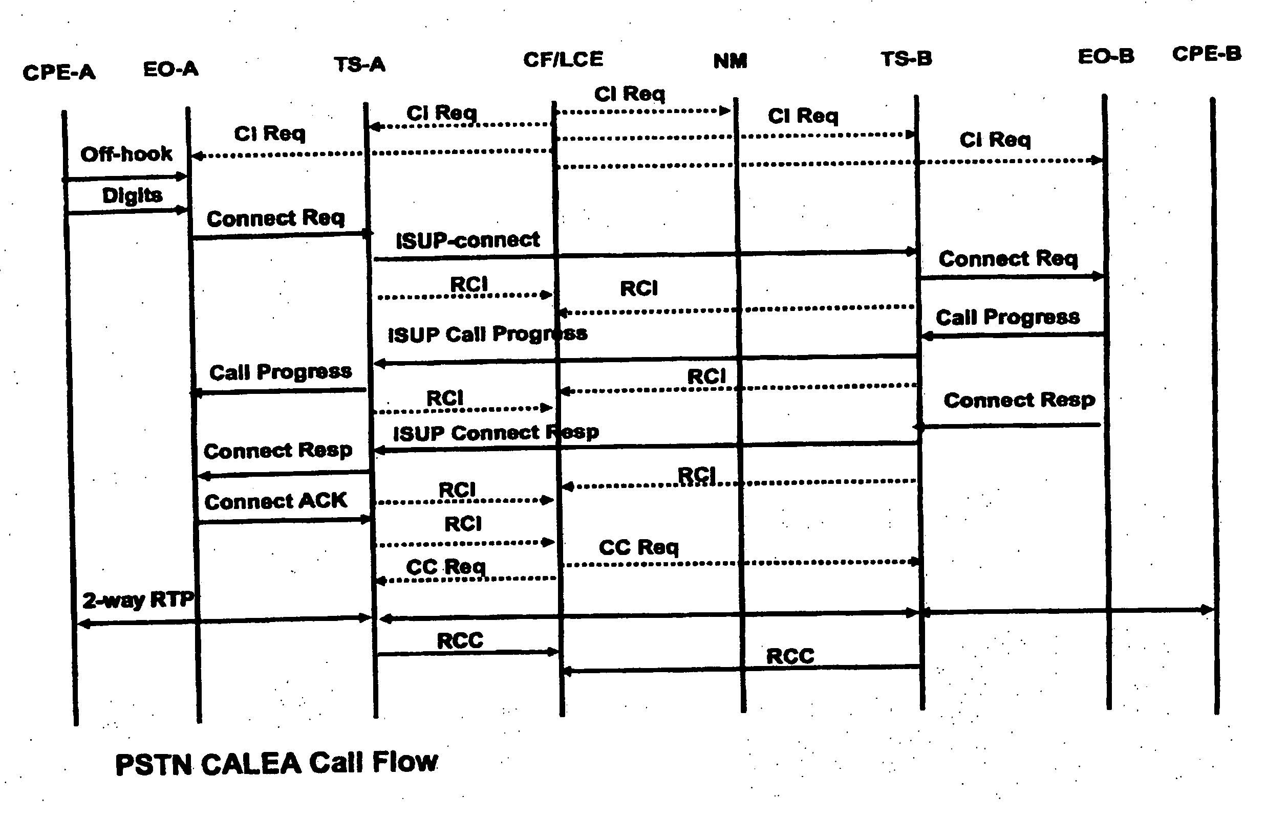
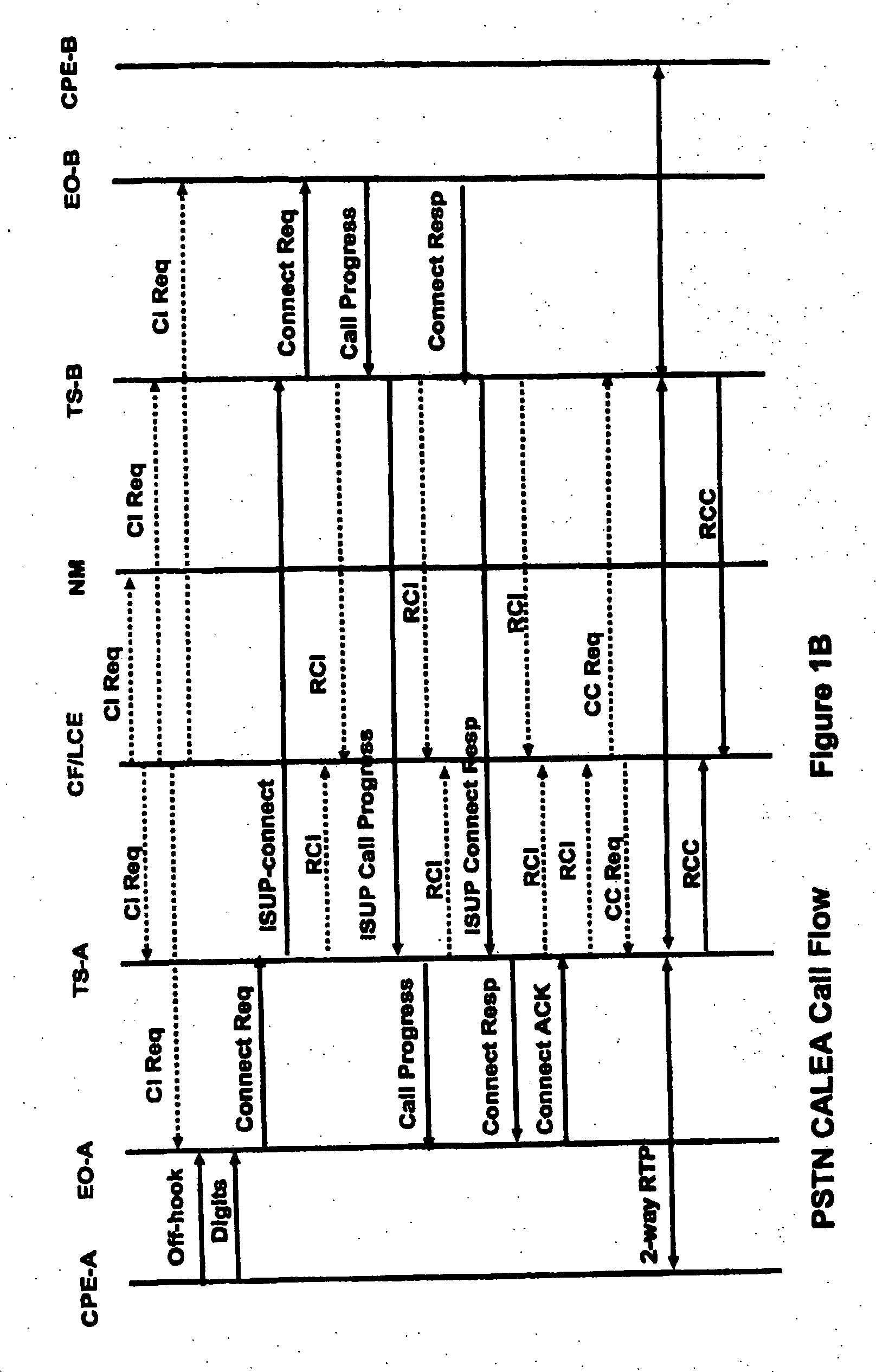
[0177] In a first exemplary embodiment, FIG. 4A depicts a managed VoP network (10), administered by a service provider, wherein an end-user device (11) (either a PC (11A) or a telephone (11B)) may place or receive packet-based telephone calls either within the network, or alternatively, through the network to a public switched telephone network (PSTN) (12). In the first embodiment, Step 1 of the analysis procedure (analysis of the network) reveals that user device 11 is connected to network 10 via a media gateway (13), an access network (14) and finally an edge router (15). Step 1 also reveals that network 10 further comprises the VoP-capable devices of a call server (16), an audio server (17) and a trunk gateway (31). Finally, the procedure reveals that the entire VoP network 10 is being managed by a network management system (18). Note that calls generally involve two or more parties with two or more end-user devices, gateways and access networks. These additional devices, gateway...

second embodiment

[0188] In a second exemplary embodiment, FIG. 5A depicts a managed VoP network (100), administered by a service provider, wherein an end-user device (111) (either a PC (111A) or a telephone (111B)) may place or receive packet-based telephone calls either within the network, or alternatively, through the network to a public switched telephone network (PSTN) (112). In the second embodiment, Step 1 of the analysis procedure (analysis of the network) reveals that the end-user device 111 is connected to network 100 via a media gateway (113), an access network (114) and finally an edge router (115). Step 1 also reveals that network 100 further comprises the VoP-capable devices of a call server (116), a centralized media gateway (117) and a trunk gateway (131). Finally, the procedure reveals that the entire VoP network 100 is being managed by a network management system (118). Note that calls generally involve two or more parties with two or more end-user devices, gateways and access netwo...

third embodiment

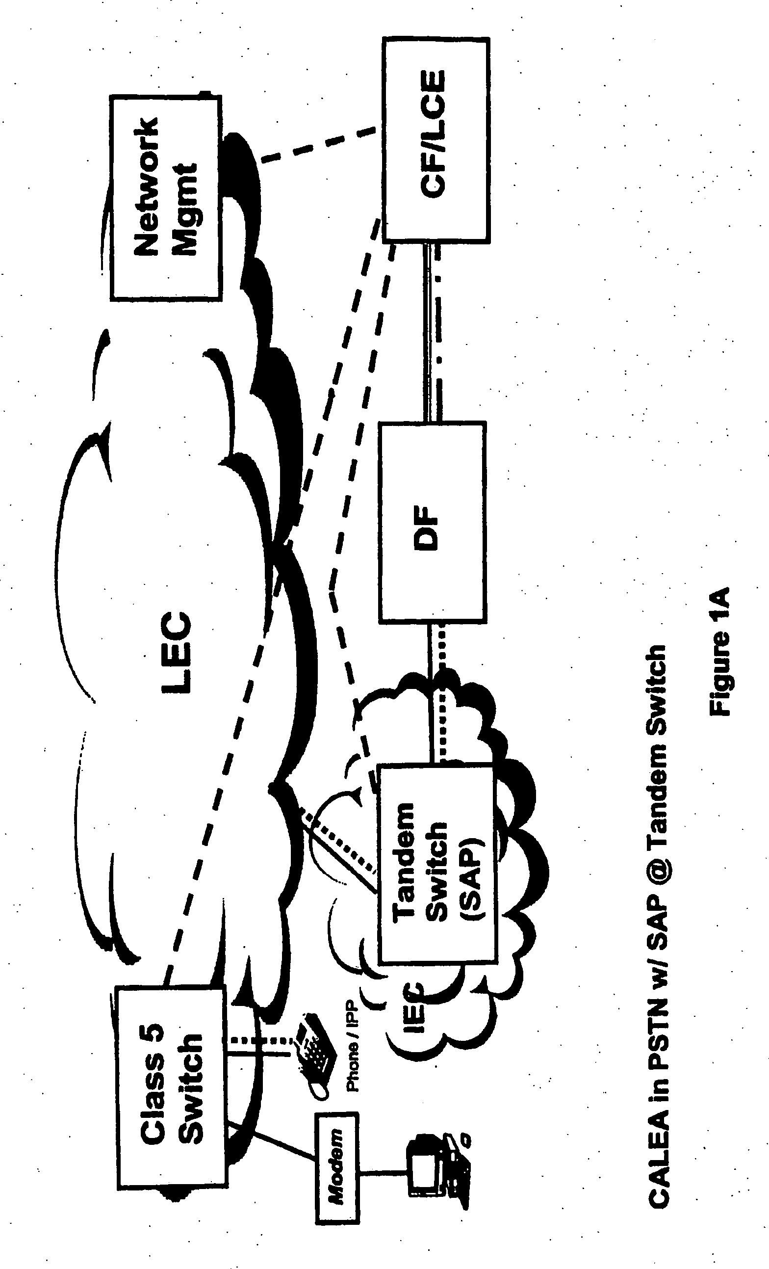
[0201] As a result of the analysis of the network of the third embodiment performed during procedure Step 1 above, media gateway 213 and call server 216 are identified as suitable SAPs during procedure Step 2. The precise nature of the Step 1 analysis and Step 2 SAP identification is beyond the scope of this discussion. Both steps are performed internal to the LEA in cooperation with the service provider. The network analysis and identification of SAPs is based on LEA assumptions regarding the nature and use of the targeted user device 211, the media gateway 213, the access network 214 and the physical and operational features of network 200.

[0202] In Step 3 of the procedure, media gateway 213 and call server 216, collectively, exemplary SAP devices 213 / 216, are configured by the service provider as part of DF 219 to permit interface with CF / LCE 220. In this embodiment, configuration of the media gateway, which may physically exist on the end-user's premises, can occur via factory-i...


PUM


Abstract

A network infrastructure device in a voice over packet (VOP) network includes a transceiver and a processor. The transceiver can transmit and receive communications over a VOP network. The processor, responsive to receipt of a call setup information request (CIReq) specifying a particular target, can associate a public identifier with the particular target, and map the public identifier to an internet protocol (IP) address responsive to a communication. Also, the processor can identify communications to and/or from the particular target with the IP address. Further, responsive to receiving communications to and/or from the IP address, the processor can transmit the communications to a law enforcement agency (LEA) collection device.

Description

CROSS-REFERENCE TO RELATED APPLICATIONS [0001] This application is a continuation-in-part of U.S. patent application Ser. No. 11 / 054,969, filed Feb. 10, 2005, which claims the benefit of the following Provisional applications: 60 / 543,755 filed Feb. 11, 2004; 60 / 545,549 filed Feb. 18, 2004; 60 / 624,668 filed Nov. 8, 2004; and 60 / 626,595 filed Nov. 10, 2004, all of which are expressly incorporated herein by reference.STATEMENT REGARDING FEDERALLY SPONSORED RESEARCH OR DEVELOPMENT [0002] Not applicable. FIELD OF THE INVENTION [0003] The present invention relates in general to the communication networks, and more specifically to surveillance of communications on voice-over-packet (VOP) networks. BACKGROUND OF THE INVENTION [0004] The Communications Assistance for Law Enforcement Act (CALEA) requires that communications networks provide means to support electronic surveillance of communications traffic. For example, surveillance can be readily accomplished in a public switched telephone n...

Claims


Application Information

Patent Timeline
IPC IPC(8): G06F15/16H04L1/00H04L29/06H04L29/12H04M3/22H04M7/00
CPCH04L29/1233H04L61/25H04L63/0428H04L63/30H04M3/2281H04M7/006H04M3/22H04M7/00H04L69/22H04L65/1046H04L65/1023H04L61/00G06F15/16H04L9/40
Inventor SCOGGINS, SHWU-YAN CHANGSINDHWANI, MANOJRAJA, CHANDER
Owner TEXAS INSTR INC
Why Eureka
Try Eureka