Ignition coil driver device with slew-rate limited dwell turn-on

a technology of ignition coil and driver device, which is applied in the direction of electric control, machines/engines, mechanical equipment, etc., can solve the problems of poor coil performance and pre-combustion, and achieve the effects of reducing the rate of voltage change across the coil primary, reducing the magnitude of secondary voltage oscillation, and slowing down the ra

Inactive Publication Date: 2006-09-28
MICHIGAN MOTOR TECH LLC
View PDF44 Cites 14 Cited by
  • Summary
  • Abstract
  • Description
  • Claims
  • Application Information

AI Technical Summary

Benefits of technology

[0013] With the proposed soft turn-on, the first transistor transits to its saturated state through the linear range at a significantly slower rate greatly reducing the rate of voltage change across the coil primary. The secondary voltage oscillation magnitude is greatly reduced.

Problems solved by technology

One problem is that the sharp turn-on during the charging cycle causes an oscillation on the secondary side 18 of the ignition coil 10. FIG. 3 illustrates the dwell command signal 24, the dwell current 26, the primary side (low-side) voltage 28, and the undesirable secondary voltage oscillation 30.
If the oscillation magnitude exceeds a tolerable level, an unintended spark event can occur across the spark plug gap, resulting in premature combustion.
One way to control the magnitude of the secondary oscillations is adding constraints in design of the ignition coil 10 resulting in poor coil performance.

Method used


Image

  • Ignition coil driver device with slew-rate limited dwell turn-on
  • Ignition coil driver device with slew-rate limited dwell turn-on
  • Ignition coil driver device with slew-rate limited dwell turn-on

Examples


Embodiment Construction

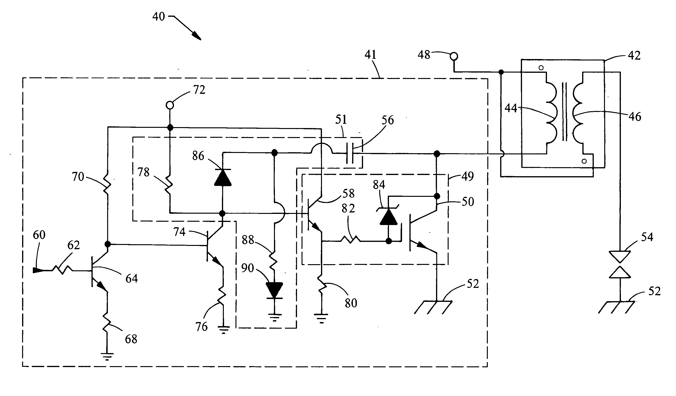
[0021] A system embodying the principles of the present invention is illustrated in FIG. 4 and designated at 40. The system 40 includes an ignition coil 42, spark plug 54, and a circuit 41 including a switching portion 49 and a rate limiting portion 51.

[0022] The switching portion 49 can be implemented on the high-side of the primary or on the low-side. A low-side driver implementation will be illustrated for discussion purposes; however the same principles can be applied to a high-side driver.

[0023] Ignition coil 42 includes a primary side 44 and a secondary side 46. The positive terminals of the primary side 44 and secondary side 46 are connected to a power source 48, generally the automotive battery. The negative terminal of the primary side 44 of the ignition coil 42 is connected to a switching portion 49 of the circuit 41. For the embodiment shown in FIG. 4, the switching portion 49 includes a first transistor 50 and a second transistor 58. The first transistor 50 is shown as...


PUM


Abstract

A device to control the charging rate of an ignition coil for an internal combustion spark ignition engine. The device controls the turn-on rate of the primary coil by slew-rate limiting using switching devices and a Miller-effect capacitor in order to reduce secondary oscillation magnitudes originated by a sharp transition of the controlling switch.

Description

BACKGROUND [0001] 1. Field of the Invention [0002] The present invention generally relates to a circuit for driving a flyback transformer, also referred to as an ignition coil, of a spark ignited internal combustion engine. More specifically it is related to controlling the turn-on rate of the ignition coil. [0003] 2. Description of Related Art [0004] In a spark ignited internal combustion engine, ignition coils provide the voltage required for electrical current to jump across a spark plug gap, igniting an air-fuel mixture in the engine cylinder causing combustion. A switch, also referred to as a coil driver, is used on the primary side of the ignition coil to control the charge and discharge cycles of the ignition coil. [0005] A typical ignition system is illustrated in FIG. 1. The system includes an ignition coil 10 having a primary side 16 and a secondary side 18. The positive terminals of the primary side 16 and secondary side 18 of the ignition coil 10 are connected to a power...

Claims


Application Information

Patent Timeline
Patent Type & Authority Applications(United States)
IPC IPC(8): F02P3/04
CPCF02D2041/2034F02D2041/2048Y02T10/142F02P3/051F02P3/0453Y02T10/12
Inventor MORAN, KEVIN D.ZHU, GUOMING G.NATION, MICHAEL T.
Owner MICHIGAN MOTOR TECH LLC
Why Eureka
Try Eureka