Method for detecting and decoding a signal in a MIMO communication system

a communication system and signal detection technology, applied in the field of wireless communication systems, can solve the problems of low reliability of received signals, high processing complexity of equalization, and distortion degrading the detection accuracy of received symbols, so as to improve the reliability of received signals

Inactive Publication Date: 2006-09-28
SAMSUNG ELECTRONICS CO LTD +1
View PDF7 Cites 29 Cited by
  • Summary
  • Abstract
  • Description
  • Claims
  • Application Information

AI Technical Summary

Benefits of technology

[0009] Accordingly, the present invention has been designed to solve the above and other problems occurring in the prior art. It is an object of the present invention to provide a method for detecting and decoding a signal that can improve the reliability of a received signal by detecting the signal while considering a decision error in an equalization process for the received signal.
[0010] It is another object of the present invention to provide a method for detecting and decoding a signal that can improve system performance by optimizing a signal detection order for channel-by-channel layers.
[0011] It is yet another object of the present invention to provide a method for detecting and decoding a signal that can reduce complexity by setting a signal detection order for one channel and applying the set signal detection order to all channels.

Problems solved by technology

This distortion degrades the detection accuracy of a received symbol, and it is an important noise factor affecting a system designed to operate in a high Signal-to-Noise Ratio (SNR) environment.
This equalization requires high processing complexity.
Therefore, when the OFDM scheme is applied to the MIMO system, the ISI is not considered for all practical purposes.
However, the conventional V-BLAST scheme has a severe drawback.
There is performance degradation due to error propagation, which is inherent in a decision feedback process.
However, these methods create new problems, such as increased processing complexity of a receiving stage.
This complexity increases according to a modulation level and the number of antennas.

Method used


Image

  • Method for detecting and decoding a signal in a MIMO communication system
  • Method for detecting and decoding a signal in a MIMO communication system
  • Method for detecting and decoding a signal in a MIMO communication system

Examples


first embodiment

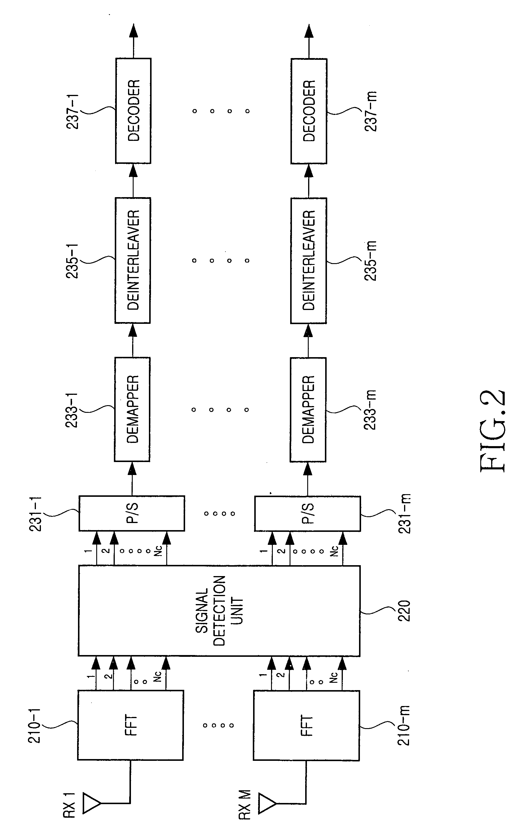
[0040]FIG. 2 illustrates a structure of a receiver of the coded layered space-time OFDM system to which the signal detection and decoding method of the present invention is applied in accordance with the present invention.

[0041] In FIG. 2, the OFDM receiver is provided with Fast Fourier Transform (FFT) processors 210-1˜210-m for performing FFT processes for signals received through MR receive antennas RX 1˜RX M, a signal detection unit 220 for processing parallel signals output from the FFT processors 210-1˜210-m and outputting parallel signal streams associated with the FFT processors 210-1˜210-m, and signal processing units for processing the parallel signal streams output from the signal detection unit 220 according to signals associated with the FFT processors 210-1˜210-m. The signal processing units are configured by Parallel-to-Serial (P / S) converters 231-1˜231-m for converting the parallel signals associated with the FFT processors 210-1˜210-m to serial symbol streams, demapp...

second embodiment

[0093]FIG. 4 illustrates a structure of a receiver of the coded layered space-time OFDM system to which the signal detection and decoding method is applied in accordance with the present invention.

[0094] In FIG. 4, an FFT processor (not illustrated), a signal detection unit 431, a P / S converter 433, a demapper 435, a deinterleaver 437, and a decoder 439 in the receiver in accordance with the second embodiment of the present invention have the same structures as those in the receiver of the first embodiment. The receiver of the second embodiment further includes a representative layer order decision unit 440 for deciding the layer order for an identical subchannel in output signals of the FFT processors and outputting a signal to the signal detection unit 431 in the decided order. The receiver of the second embodiment further includes a second encoder 441 for encoding an output signal of the decoder 439 through the same encoding scheme as that of an associated transmitter, a second i...


PUM


Abstract

A method for detecting and decoding a signal in a communication system based on Multiple-Input Multiple-Output (MIMO)-Orthogonal Frequency Division Multiplexing (OFDM). A signal is received through multiple receive antennas. A decision error occurring at a symbol decision time is considered and a symbol is detected from transmitted symbols. Original data transmitted from the detected symbol is recovered. The performance of a coded bit system can be significantly improved using a new equalization matrix G considering a decision error.

Description

PRIORITY [0001] This application claims priority under 35 U.S.C. § 119 to an application entitled “Method for Detecting and Decoding a Signal in a MIMO Communication System” filed in the Korean Intellectual Property Office on Mar. 22, 2005 and assigned Serial No. 2005-23795, the contents of which are incorporated herein by reference. BACKGROUND OF THE INVENTION [0002] 1. Field of the Invention [0003] The present invention generally relates to a wireless communication system, and more particularly to a method for detecting and decoding a signal in a Multiple-Input Multiple-Output (MIMO) communication system. [0004] 2. Description of the Related Art [0005] A Multiple-Input Multiple-Output (MIMO) communication system transmits and receives data using multiple transmit antennas and multiple receive antennas. A MIMO channel formed by Nt transmit antennas and Nr receive antennas is divided into a plurality of independent spatial subchannels. Because the MIMO system employs multiple transm...

Claims


Application Information

Patent Timeline
Patent Type & Authority Applications(United States)
IPC IPC(8): H04L1/02H04B7/02
CPCH04L1/0656H04L27/2647H04L2025/03414H04L27/265H04L27/2628H04L1/0071H04L27/01H04L27/2697
Inventor LEE, DONG-JUNLEEAHN, MIN-YOUNGKIM, JONG-HANLEE, HEUN-CHUL
Owner SAMSUNG ELECTRONICS CO LTD
Why Eureka
Try Eureka