Particulate sampler system flow calibration

a sampler and flow calibration technology, applied in the direction of volume flow testing/calibration, fluorescence/phosphorescence, instruments, etc., can solve the problem of poor accuracy above the desired five percent, and achieve the effect of improving the overall accuracy of the sampler system

Inactive Publication Date: 2006-09-28
AVL TEST SYST
View PDF2 Cites 3 Cited by
  • Summary
  • Abstract
  • Description
  • Claims
  • Application Information

AI Technical Summary

Benefits of technology

[0008] The diluted exhaust mass flow controller is calibrated and calibration coefficients are generated using a first to fourth order curve fit. Similarly, initial calibration coefficients are generated for the dilution mass flow controller. The diluted exhaust mass flow controller is set at a desired flow point. The dilution mass flow controller is varied between set points corresponding to different dilution ratios at the common, desired set point. The data obtained is used to determine a correction factor for example, by performing a linear curve fit of the data. The correction factor is applied to the calibration coefficients associated with the mass flow controllers. In this manner, the transfer error is addressed and the overall accuracy of the particulate sampler system is improved.

Problems solved by technology

This results in what is referred to as a transfer error which can result in an accuracy that is worse than the desired five percent.

Method used


Image

  • Particulate sampler system flow calibration
  • Particulate sampler system flow calibration
  • Particulate sampler system flow calibration

Examples


Embodiment Construction

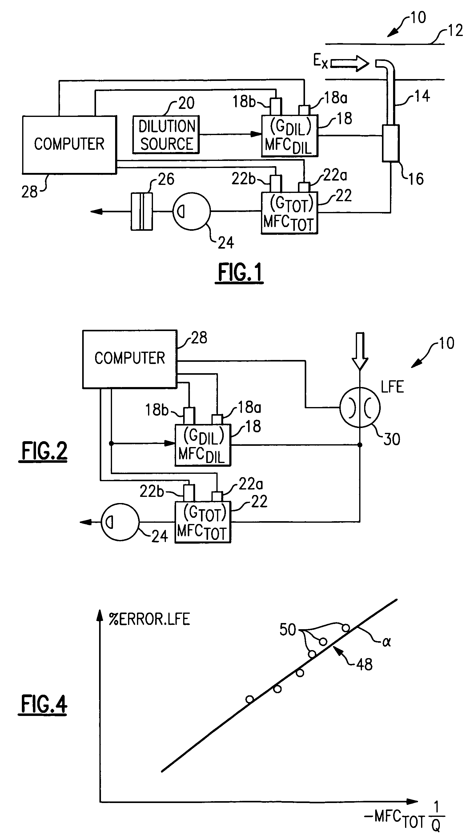
[0015] A schematic of a particulate sampler system 10 during a test procedure is shown in FIG. 1. The system 10 includes exhaust pipe 12 that carries exhaust from an emissions source such as a diesel engine in a vehicle. A probe 14 receives a portion of the exhaust for analysis. A diluent such as nitrogen flows from a dilution source 20 through a dilution mass flow controller 18 into a tunnel 16 where it mixes with the exhaust sample. The diluted exhaust sample flows through a diluted exhaust mass flow controller 22. A pump 24 draws the fluid through the system 10. The diluted exhaust sample flows through a filter 26 upon which particulates in the sample collect. The filter is later weighed to determine the mass of particulates within the sample. The total particulates are calculated, in part, by taking the difference of the mass flow measured by the diluted exhaust mass flow controller 22 and dilution mass flow controller 18 to determine the mass flow of the exhaust sample. Of cour...


PUM

PropertyMeasurementUnit
DIAMETERaaaaaaaaaa
constant flow rateaaaaaaaaaa
sizeaaaaaaaaaa

Abstract

A particulate sampler system includes a diluted exhaust mass flow controller that receives flow from a dilution mass flow controller and a laminar flow element (LFE). The dilution mass flow controller and LFE are fluidly arranged parallel to one another. A controller communicates with the mass flow controllers and the LFE to determine the flow through these devices, command valves in the mass flow controllers and generate data for determining calibration coefficients and correction factors. The diluted exhaust mass flow controller is calibrated and calibration coefficients are generated using a first to fourth order curve fit. Similarly, initial calibration coefficients are generated for the dilution mass flow controller. The diluted exhaust mass flow controller is set at a desired flow point. The dilution mass flow controller is varied between set points corresponding to different dilution ratios at the common, desired set point. The data obtained is used to determine a correction factor for example, by performing a linear curve fit of the data. The correction factor is applied to the calibration coefficients associated with the mass flow controllers.

Description

[0001] This application corresponds to U.S. Provisional Application Ser. No. 60 / 664,277, filed Mar. 22, 2005. BACKGROUND OF THE INVENTION [0002] This invention relates to a method and apparatus for calibrating a particulate sampler system used in quantifying particulates from vehicle emissions. [0003] Particulate sampler systems are used to quantify emission particulates from, for example, diesel engines for vehicles. The systems are used for engine development and to ensure compliance with governmental regulations concerning emissions of particulate matter. [0004] The particulate sampler system must be calibrated to ensure its accuracy so that test results are reliable. The test procedures, calibration, and accuracies are often specified by various regulations and standards, such as ISO 16183. It is desirable to have better than five percent accuracy. [0005] One typical particulate sampler system includes a probe that obtains a sample from an exhaust source. The sample is diluted u...

Claims


Application Information

Patent Timeline
Patent Type & Authority Applications(United States)
IPC IPC(8): G01N21/64
CPCG01F25/0007G01N1/2252G01N5/02Y10T436/10G01N35/00693G01N2001/2223G01N2001/225G01N15/0272G01F25/10
Inventor MAREK, GERALDNUDEHI, SHAHIN SABOKDAST
Owner AVL TEST SYST
Why Eureka
Try Eureka