Stent

Active Publication Date: 2006-09-28
ADMEDES SCHUESSLER
View PDF31 Cites 68 Cited by
  • Summary
  • Abstract
  • Description
  • Claims
  • Application Information

AI Technical Summary

Benefits of technology

[0006] One embodiment of the present invention provides an improved aneurysm stent

Problems solved by technology

This limitation of the flow rate results in thrombogenesis of the

Method used


Image

  • Stent
  • Stent
  • Stent

Examples


Example

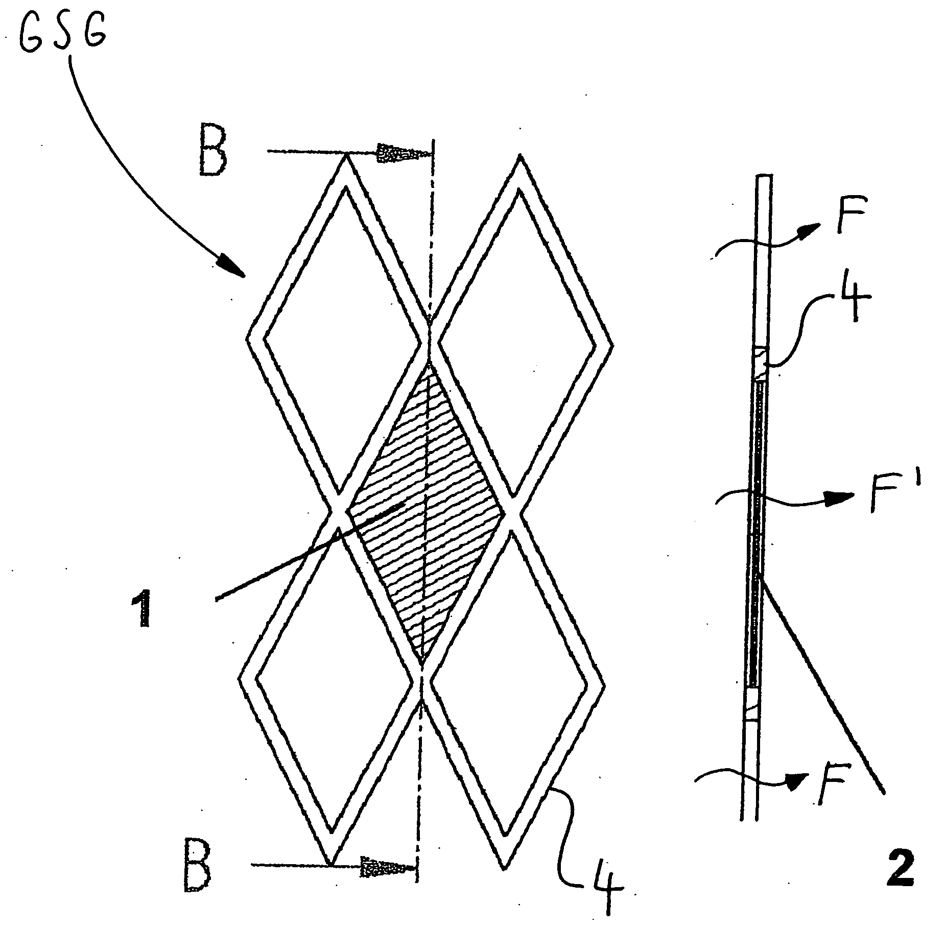
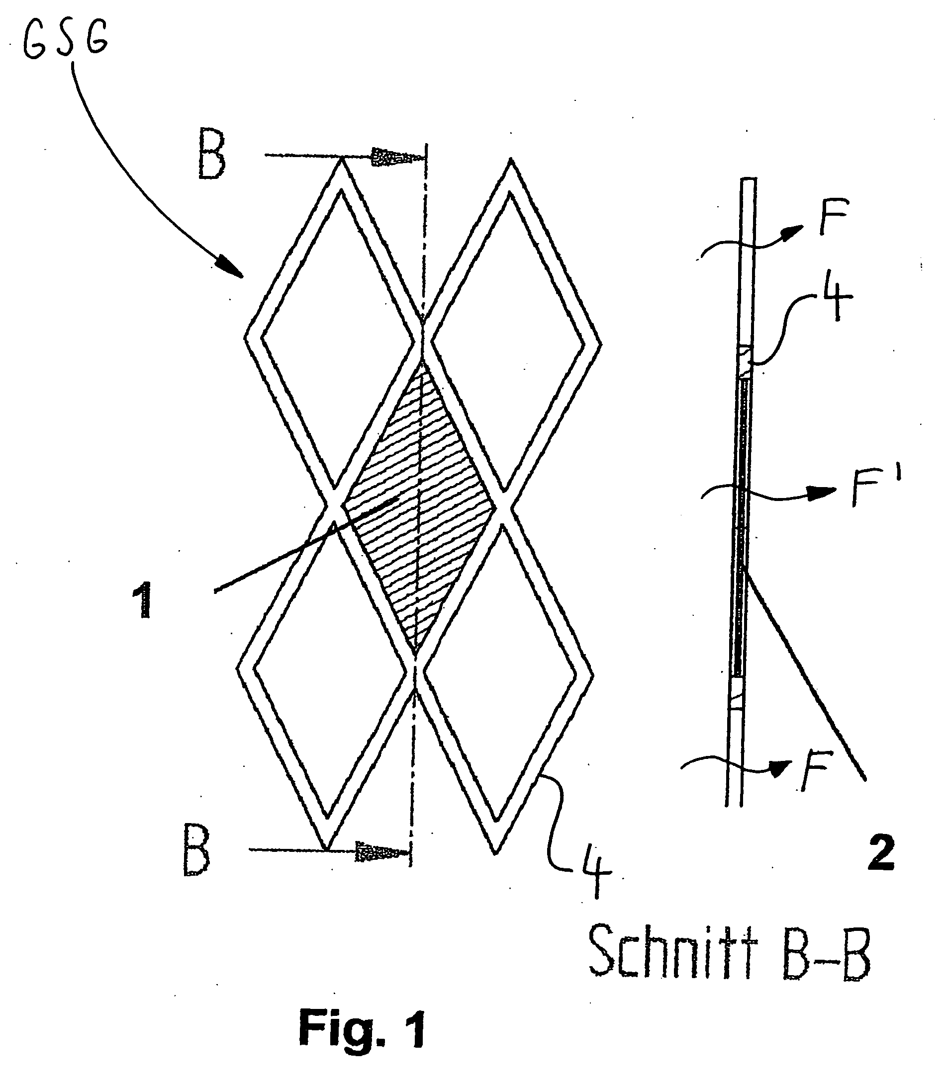
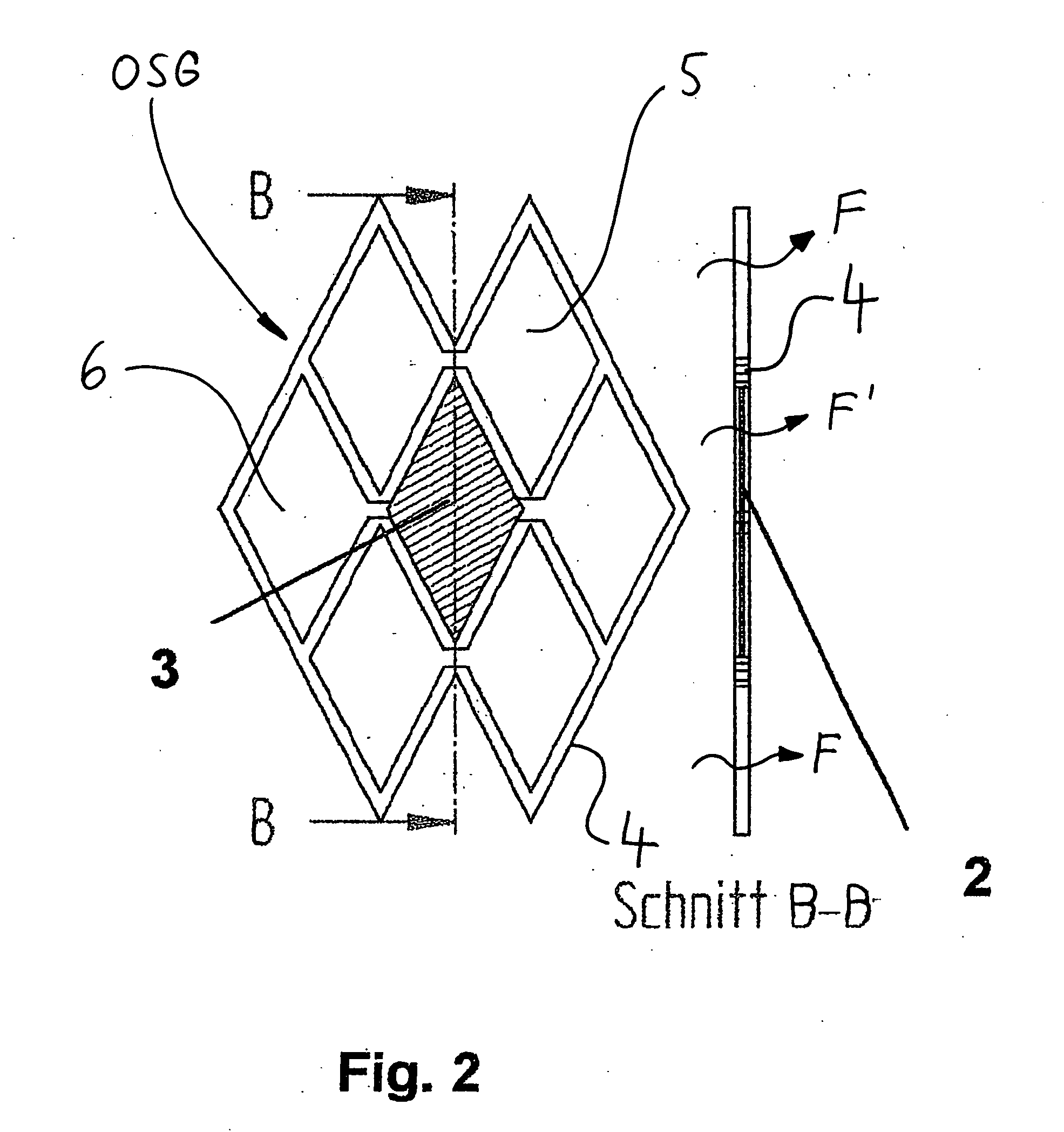
[0034] As shown in FIGS. 1 and 2, an aneurysm stent according to the invention has a covered stent cell 1, 3 which is at least partially covered by a membrane 2 by the fact that the membrane 2 is inserted into the stent cell 1, 3 and is attached to the webs 4 of the cell 1, 3. The configuration of the membrane 2 to form a partially covered stent is possible for a stent having a closed stent cell geometry CSG, as shown in FIG. 1, as well as for a stent having an open stent cell geometry OSG, as shown in FIG. 2. The open stent cell geometry OSG may have two, three, or more stent cells 3. FIG. 2 shows an open stent cell geometry OSG having two connected stent cells, i.e., open stent cells 5 and an open stent cell geometry OSG, with three connected stent cells 6.

[0035] The stent has essentially unhindered fluid permeability in the radial direction through its non-covered stent cells, as indicated by F in FIGS. 1 and 2, and has reduced, eliminated, or interrupted fluid permeability in t...


PUM


Abstract

The present invention relates to an aneurysm stent for implantation into a living body, in particular for treatment of aneurysms, in order to implant the stent in the compressed state in a vessel and expand the stent after positioning it in the vessel, having a grid or mesh structure and at least one membrane (2) or a plurality of membranes (2) for covering at least one or more stent cells (1; 3) in the grid or mesh structure, thereby matching the permeation characteristics of the stent structure to the particular characteristics of the aneurysm.

Description

CROSS-REFERENCES TO RELATED APPLICATIONS [0001] The present application claims priority to German Application No. 10-2005-013547.1-43, filed Mar. 23, 2005, which is incorporated herein by reference. BACKGROUND OF THE INVENTION [0002] The present invention relates to a stent system for implantation into a living body, in particular as an aneurysm stent system or endoprosthesis for intracerebral aneurysms. [0003] Intracerebral aneurysms are the most common cause of non-traumatic subarachnoid hemorrhaging. The incidence is 1% in the general population, and, according to autopsy studies, as high as 9%. From a pathomorphological standpoint, intracerebral aneurysms as a rule are genuine saccular aneurysms, which are usually localized in vascular arborizations (see, for example, Schumacher, M., “Diagnostic workup in cerebral aneurysms” in Nakstadt PHj (ed): “Cerebral Aneurysms,” pp. 13-24, Bologna: Centauro (2000)). [0004] EP 0737452 describes a stent having additional interwoven threads t...

Claims


Application Information

Patent Timeline
IPC IPC(8): A61F2/06A61F2/82A61F2/91A61F2/915
CPCA61F2/91A61F2/915A61F2002/823A61F2002/91541A61F2002/91558
Inventor MAILANDER, WERNERFLAXMEIER, ERIKSTEINER, RALPHSCHERRIBLE, FRANK
Owner ADMEDES SCHUESSLER
Why Eureka
Try Eureka