Protective tape separating method and apparatus using the same
a technology of protective tape and separation method, which is applied in the direction of door/window protective device, mechanical control device, instruments, etc., can solve the problems of separation error and inability to smoothly separate protective tape from the end edg
- Summary
- Abstract
- Description
- Claims
- Application Information
AI Technical Summary
Benefits of technology
Problems solved by technology
Method used
Image
Examples
embodiment 1
Another Embodiment 1
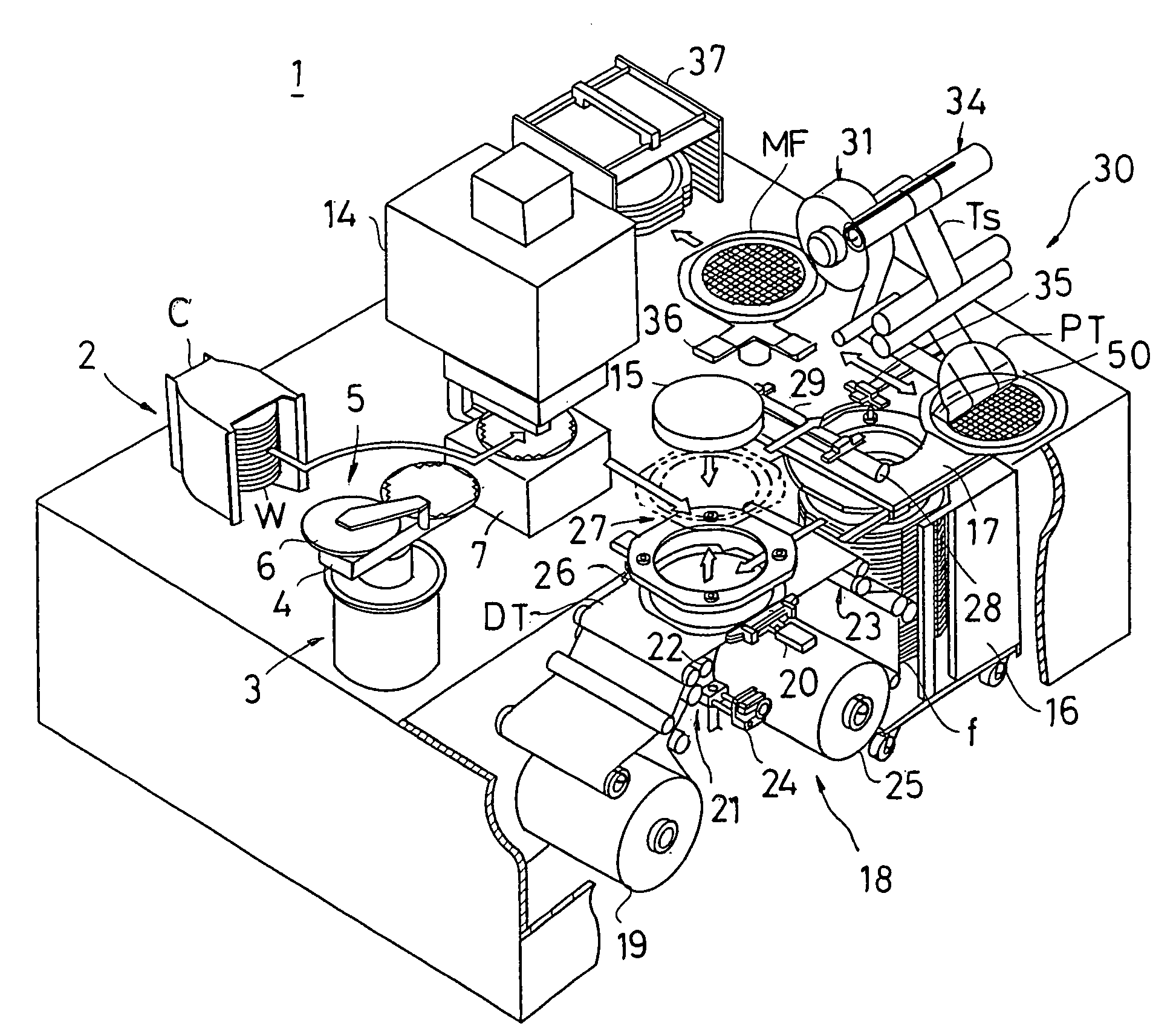
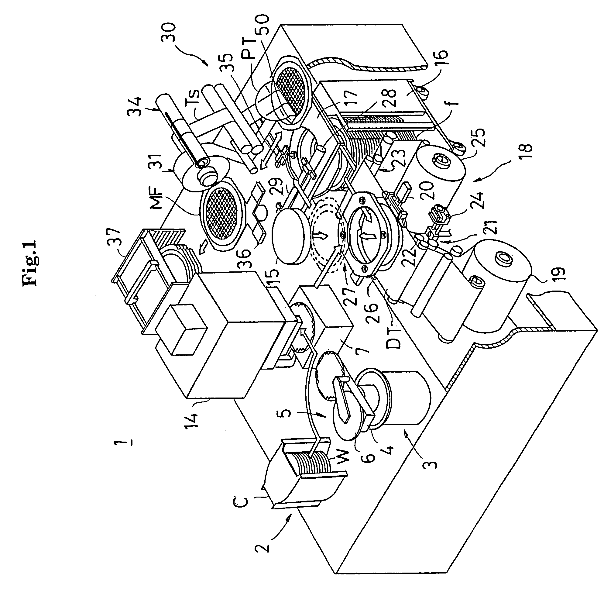
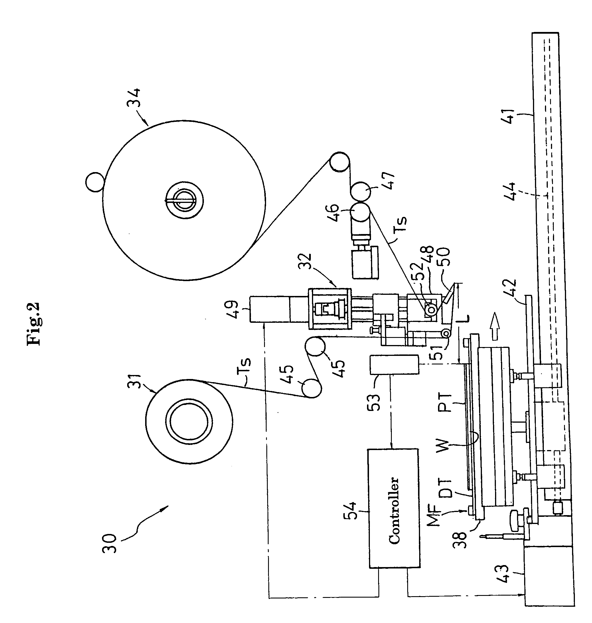
[0117] In the above embodiment, while the mount frame MF moves forward to pass through the position under the separation unit 32, the edge member 50 simultaneously joins and separates the separation tape Ts to and from the protective tape PT. However, it is also possible to join and separate the separation tape Ts to and from the protective tape PT in separate processes in order and there is one example shown in FIGS. 9 to 12.
[0118] In this embodiment, while the separation table 38, the tape supply unit 31, and the tape collection unit 34 are respectively disposed in fixed positions, the separation unit 32 of the separation mechanism 30 and the photosensor 53 provided to the separation unit 32 are moved horizontally forward / backward by a drive mechanism (not shown) and are actuated as follows.
[0119] First, as shown in FIG. 9, the separation unit 32 is moved forward from a standby position displaced from the separation table 38 and, during the movement, the fron...
embodiment 2
Another Embodiment 2
[0125] In this embodiment, a case in which thermosetting adhesive tape is used as the separation tape Ts, the separation tape Ts is joined to the protective tape PT with the edge member 50, and the separation tape Ts and the protective tape PT are separated together from the wafer W will be described as an example. Therefore, this embodiment is different from the above embodiment in configurations of the separation tape Ts supplied from the tape supply unit 31 and the edge member 50 shown in FIG. 1 and is similar to the above embodiment in other structures. The similar configurations will merely be provided with the same reference numerals and the different configurations will be described concretely.
[0126]FIG. 13 is a perspective view showing a portion around an edge member according to the present embodiment and FIG. 14 is a plan view showing a configuration of a main portion around the edge member.
[0127] As shown in FIGS. 13 and 14, the edge member 50A is at...
PUM
| Property | Measurement | Unit |
|---|---|---|
| wavelength | aaaaa | aaaaa |
| width | aaaaa | aaaaa |
| width | aaaaa | aaaaa |
Abstract
Description
Claims
Application Information
 - R&D
- Intellectual Property
- Life Sciences
- Materials
- Tech Scout
- Unparalleled Data Quality
- Higher Quality Content
- 60% Fewer Hallucinations
Browse by: Latest US Patents, China's latest patents, Technical Efficacy Thesaurus, Application Domain, Technology Topic, Popular Technical Reports.
© 2025 PatSnap. All rights reserved.Legal|Privacy policy|Modern Slavery Act Transparency Statement|Sitemap|About US| Contact US: help@patsnap.com


