Laser bonding tool with improved bonding accuracy

Inactive Publication Date: 2006-10-05
MEDTRONIC INC
View PDF14 Cites 10 Cited by
  • Summary
  • Abstract
  • Description
  • Claims
  • Application Information

AI Technical Summary

Problems solved by technology

In such applications, heat is often employed to support the soldering or welding process; however, traditional heating methods have certain drawbacks when used in the microelectronic integrated circuit environment.
Such processes, however, may result in distortion or bending of the lead frame or damage to the electronic components being joined especially if the heat source is large compared to the area being bonded.
In this case, a bonding tool imparts high frequency vibrations to the parts being bonded resulting in metallurgical atomic diffusion bonding.
Unfortunately, ultrasonic bonding suffers certain drawbacks.
For example, ultrasonic or thermal-sonic (ultrasonic vibration in combination with the application of heat) bonding methods may find application in bonding flat, rigid structures, but are not well-suited to bond less rigid (flexible or semi-flexible) structures since such structures tend to vibrate in response to the ultras

Method used


Image

  • Laser bonding tool with improved bonding accuracy
  • Laser bonding tool with improved bonding accuracy
  • Laser bonding tool with improved bonding accuracy

Examples


first embodiment

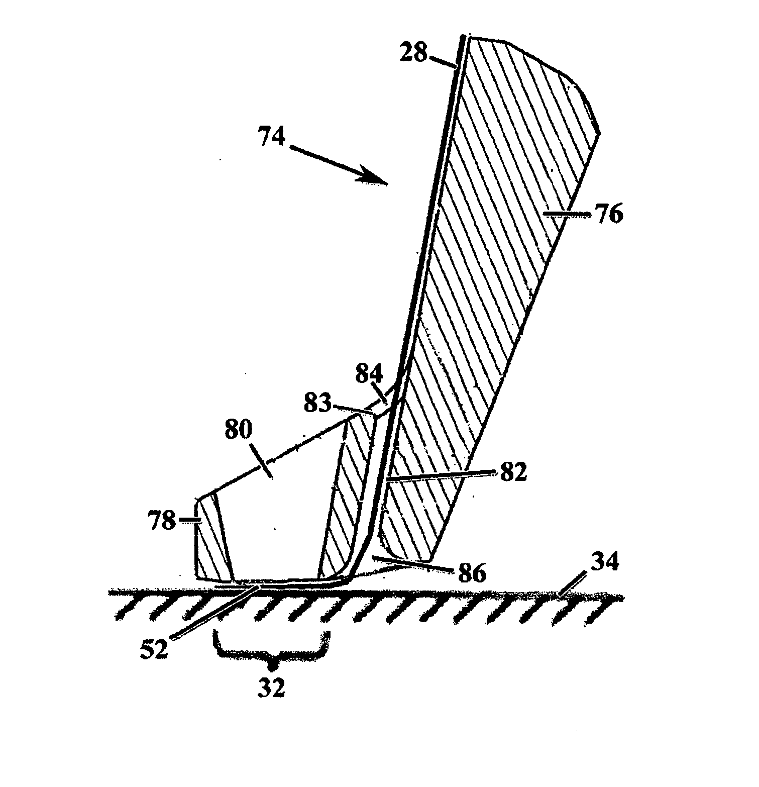
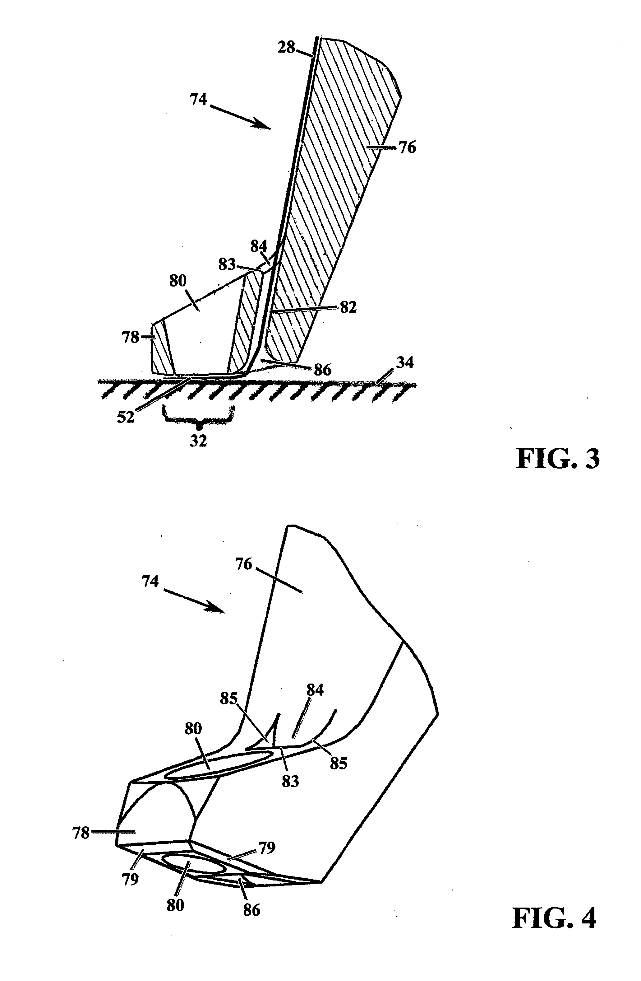
[0027]FIGS. 3 and 4 are cross-sectional and isometric views, respectively, of a bonding tool 74 in accordance with the present invention. Similar to known bonding tool 21, bonding tool 74 comprises two general portions: an elongated body portion 76 (only the bottom portion of which is shown in FIGS. 3 and 4) and a foot portion 78, which extends transversely from body portion 76 (e.g., in a forward direction). Foot portion 78 has provided therethrough a laser aperture 80 that permits section 52 of bonding ribbon 28 to be exposed to laser beam 24 (FIG. 1) and thereby bonded to a bonding site (e.g., bonding site 32 on workpiece 34 as shown in FIG. 3). To help guide ribbon 28 through foot portion 78 and beneath its working surface, bonding tool 74 further comprises a guide channel 82 therethrough having an inlet 84 and an outlet 86. Guide channel 82 is disposed between laser aperture 80 and elongated body portion 76 such that inlet 84 is provided through the upper surface of foot portio...

second embodiment

[0030]FIGS. 11 and 12 are cross-sectional side and cross-sectional isometric views, respectively, of a bonding tool 100 in accordance with the present invention. As may be most readily appreciated by comparing FIG. 10 and FIG. 3, bonding tool 100 differs from bonding tool 74 in that a cover 104 is provided along a front surface 88 of body portion 76. Cover 104 may be formed integrally with elongated body portion 76 by way of, for example, welding, application of an adhesive, or attachment via one or more fasteners (e.g., set screws). Cover 104 cooperates with front surface 88 to form a ribbon conduit or guide 102 through which ribbon 28 may pass. The entrance of ribbon guide 102 may be located near the top of cover 104 and, when cover 104 is coupled to body portion 76, the proximal end of body portion 76 (not shown in FIGS. 11 and 12). The exit of ribbon guide 102 is preferably provided near the distal end of body portion 76 just above foot portion 78 (i.e., proximate inlet 84 of gu...


PUM


Abstract

A bonding tool for use in a laser bonding apparatus comprises an elongated body portion and a foot portion coupled thereto. The foot portion extends substantially transversely from the body portion and has a laser aperture and a guide channel therethrough. The guide channel is disposed between the body portion and the laser aperture.

Description

FIELD OF THE INVENTION [0001] This invention relates generally to laser bonding, and more particularly to an improved bonding tool used in a laser bonding apparatus. BACKGROUND OF THE INVENTION [0002] Integrated circuits have become increasingly smaller, and consequently the process for electrically coupling such integrated circuits to other components (e.g., other integrated circuits) demands increasing precision. It is well known, for example, to produce electronic connections by means of soldering; i.e., melting alloy or chemical element with a relatively low melting temperature wherein the base materials of the workpieces being joined are not melted and do not become part of a joint. Alternatively, it is known to make electronic connections between components by means of welding. This involves the melting of the base workpieces to be joined resulting in the formation of a weld nugget comprised of material from both of the components being joined; i.e., by means of a fusion or mi...

Claims


Application Information

Patent Timeline
IPC IPC(8): B23K1/005B23K26/20
CPCB23K20/004H01L2224/78318B23K26/203B23K26/22B23K2201/42H01L24/45H01L24/78H01L24/85H01L2224/45014H01L2224/45124H01L2224/45144H01L2224/45147H01L2224/48091H01L2224/48472H01L2224/78302H01L2224/78313H01L2224/78314H01L2224/85205H01L2224/85214H01L2924/01013H01L2924/01029H01L2924/01057H01L2924/01079H01L2924/01082H01L2924/14B23K26/023H01L2924/01033H01L2924/014H01L2924/00014H01L2924/00B23K26/037B23K26/211H01L24/48B23K2101/42H01L2224/78261H01L2224/85207H01L2924/00015H01L2924/206
Inventor RUBEN, DAVID A.KINSEY, CHRISTOPHER T.GALVIN, JEFFREY L.SLEEPER, SCOTT B.
Owner MEDTRONIC INC
Why Eureka
Try Eureka