Light receiving amplifier circuit and optical pickup device having the same

a technology of light receiving amplifier and optical pickup device, which is applied in the direction of amplifiers with semiconductor devices only, amplifiers with semiconductor devices/discharge tubes, data recording, etc., can solve the problems of reducing the stabilization time, too long stabilization time to extract a signal contained in the disk, etc., and achieves the effect of shortening the stabilization tim

Inactive Publication Date: 2006-10-05
SHARP KK
View PDF2 Cites 18 Cited by
  • Summary
  • Abstract
  • Description
  • Claims
  • Application Information

AI Technical Summary

Benefits of technology

[0028] The present invention is made in view of the foregoing problems, and an object of the present invention is to provide a light receiving amplifier circuit capable of shortening a stabilization time while having a band limiting capacitor, and an optical pickup device having the light receiving amplifier circuit.

Problems solved by technology

This gives rise to the fact that the stabilization time is too long to extract a signal contained in the disk, even if a feedback resistor Rf (i.e., a gain) is switched during recording operation.
Therefore, a problem to be solved is to reduce the stabilization time.

Method used


Image

  • Light receiving amplifier circuit and optical pickup device having the same
  • Light receiving amplifier circuit and optical pickup device having the same
  • Light receiving amplifier circuit and optical pickup device having the same

Examples


first embodiment

[0050] With reference to FIGS. 1 and 4, an embodiment of the present invention is described below.

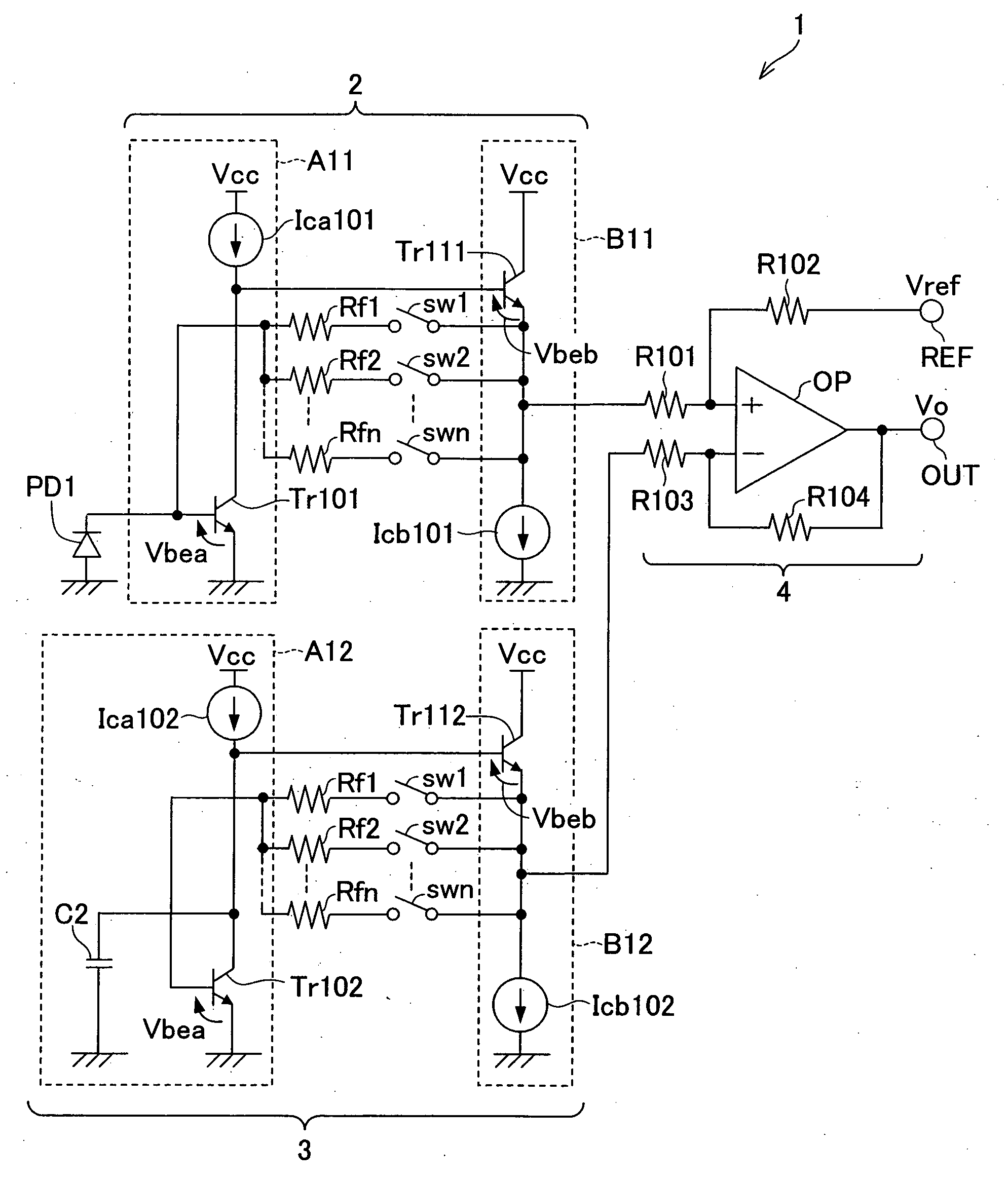
[0051]FIG. 1 illustrates a circuitry of a light receiving amplifier circuit 1 of the present embodiment. The light receiving amplifier circuit 1 can be provided in the light receiving amplifier elements 109, 110 and 111 of the optical pickup device 101 shown in FIG. 4.

[0052] The light receiving amplifier circuit 1 includes a photodiode PD1, an IV amplifier 2, a dummy amplifier 3, and a differential amplifier circuit 4.

[0053] The photodiode (light receiving element) PD1 has an anode connected to GND, and a cathode connected to a base of a transistor Tr101.

[0054] The IV amplifier 2 includes an amplifier circuit A11, an output circuit B11, and a plurality of feedback resistors Rf1, Rf2, . . . Rfn. The amplifier circuit A11 is constituted by a grounded-emitter amplifier circuit, and the output circuit B11 is constituted by an emitter follower circuit. The IV amplifier 2 converts a curre...

second embodiment

[0085] With reference to FIGS. 2 through 4, another embodiment of the present invention is described below.

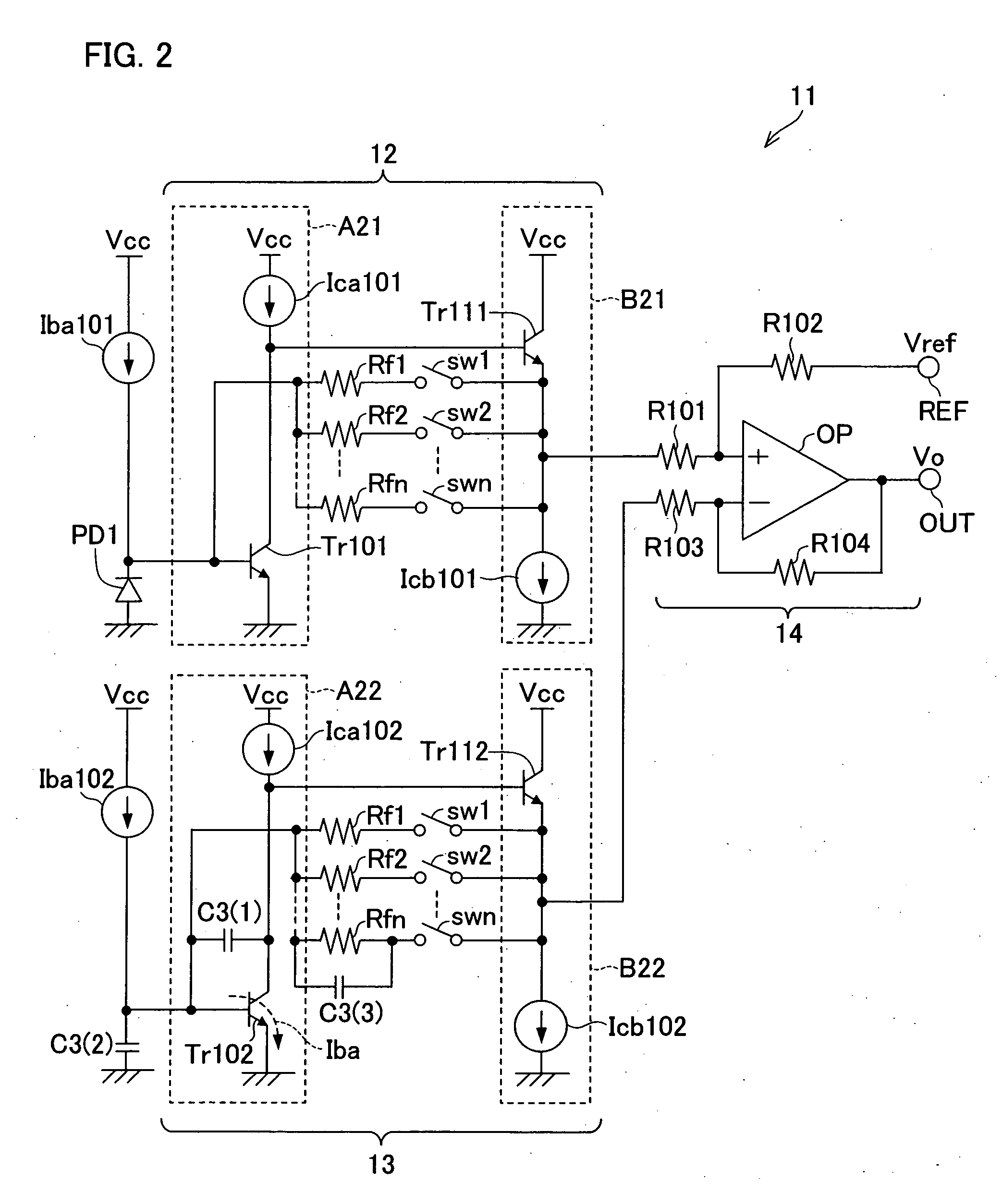
[0086]FIG. 2 illustrates a circuitry of a light receiving amplifier circuit 11 of the present embodiment. The light receiving amplifier circuit 11 can be provided in the light receiving amplifier elements 109, 110, and 111 of the optical pickup device 101 shown in FIG. 4.

[0087] The light receiving amplifier circuit 11 includes a photodiode PD1, an IV amplifier 12, a dummy amplifier 13, and a differential amplifier circuit 14.

[0088] The photodiode (light receiving element) PD1 has an anode connected to GND, and a cathode connected to a base of a transistor Tr101.

[0089] The IV amplifier 12 includes a constant current source Iba101, an amplifier circuit A21, an output circuit B21, and a plurality of feedback resistors Rf1, Rf2, . . . Rfn. The amplifier circuit A21 is constituted by an grounded-emitter amplifier circuit, and the output circuit B21 is constituted by an emitter f...


PUM


Abstract

In a light receiving amplifier circuit, a dummy amplifier has an identical structure with an IV amplifier except that the dummy amplifier is not connected to a light receiving element and includes a capacitor, i.e., a band limiting capacitor. Further, the capacitor is connected between the collector of the grounded-emitter transistor Tr and GND.

Description

[0001] This Nonprovisional application claims priority under 35 U.S.C. §119(a) on Patent Application No. 80605 / 2005 filed in Japan on Mar. 18, 2005, the entire contents of which are hereby incorporated by reference.FIELD OF THE INVENTION [0002] The present invention relates to a light receiving amplifier circuit mounted on an optical pickup device for reproducing / recording an optical disk. BACKGROUND OF THE INVENTION [0003] An optical disk recording / reproducing device includes: a light emitting element which irradiates a laser beam for reproducing / recording onto an optical disk; and a light receiving amplifier element for receiving reflected light from the optical disk. The light amplifier element contains a light receiving element and a light receiving amplifier circuit. The light receiving element receives the reflected light or monitors a laser beam emitted from a laser light source provided as a light source for recording-use and reproducing-use, and converts the light signal in...

Claims


Application Information

Patent Timeline
Patent Type & Authority Applications(United States)
IPC IPC(8): H03F3/08
CPCH03F3/08
Inventor KIJI, HITOSHI
Owner SHARP KK
Why Eureka
Try Eureka