Eureka AIR delivers breakthrough ideas for toughest innovation challenges, trusted by R&D personnel around the world.

Phase modulation for backscatter transponders

a backscatter transponder and phase modulation technology, applied in the field of radio frequency identification systems, can solve the problems of difficult design of existing passive transponders, limited range of passive transponders, and difficult detection of amplitude variation at the reader

Inactive Publication Date: 2006-10-05
MARK IV INDS
View PDF52 Cites 76 Cited by
  • Summary
  • Abstract
  • Description
  • Claims
  • Application Information

AI Technical Summary

Benefits of technology

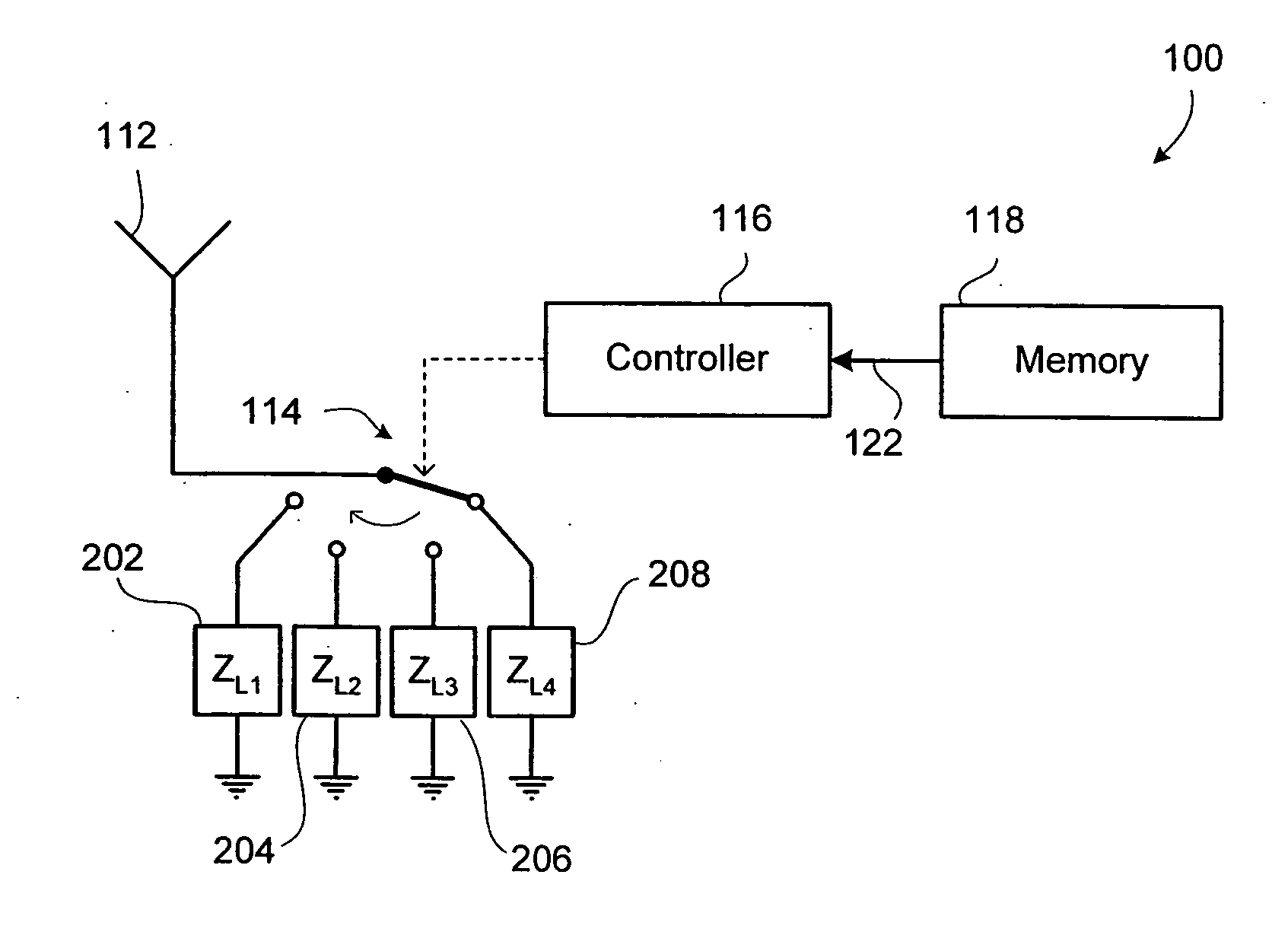
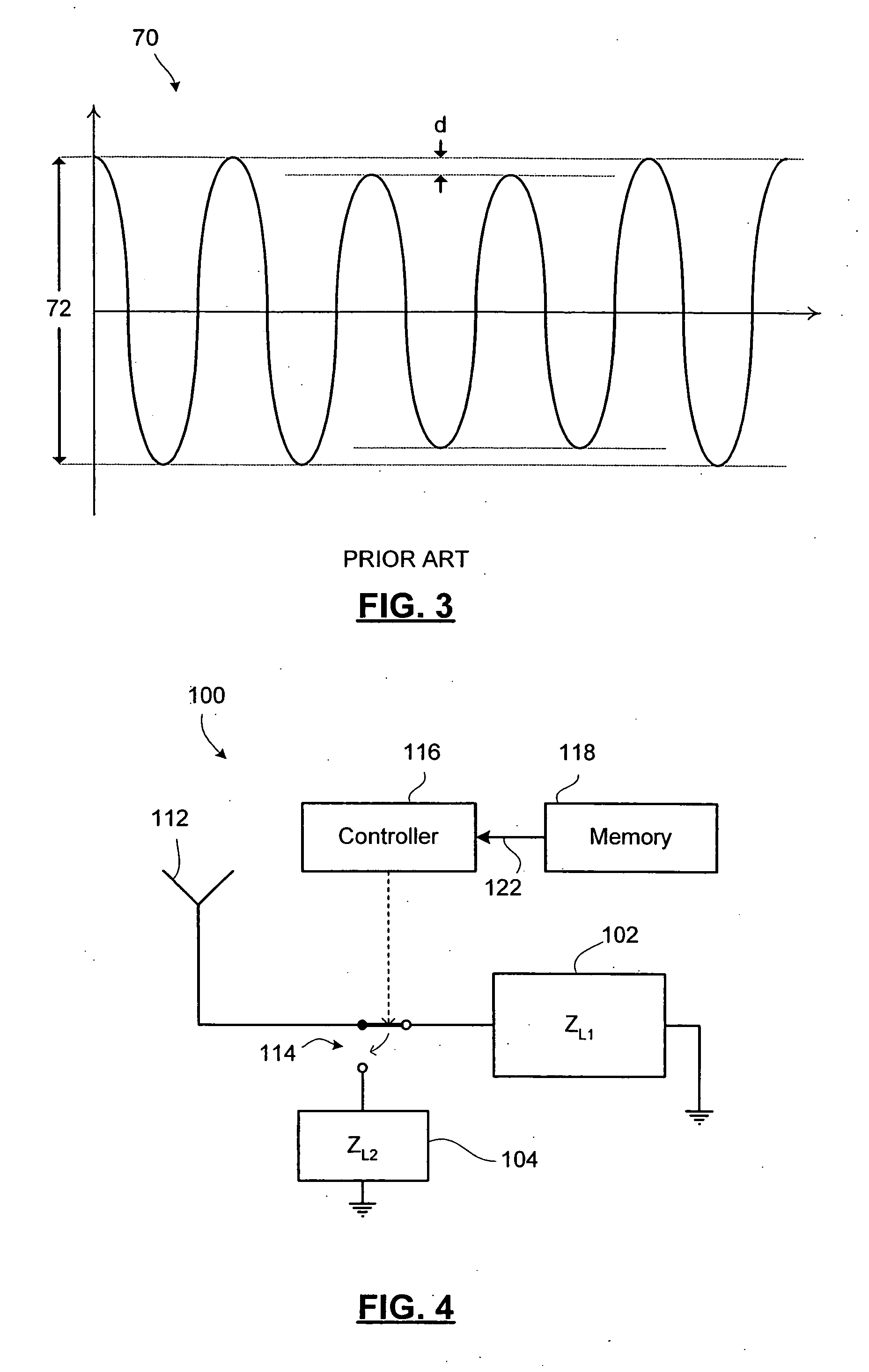
[0006] The present invention provides a radio frequency identification system having a passive backscatter transponder employing phase modulation. The transponder selectively couples its antenna to one of two or more impedances, wherein the impedances each produce a reflected signal when coupled to the antenna in the presence of a continuous RF wave from the reader. The reflected signals produced by the impedances are out-of-phase with each other. The transponder switches

Problems solved by technology

The reflected signal is small relative to the continuous wave transmitted by the reader, so it will be appreciated that this OOK amplitude variation may be relatively difficult to detect at the reader.
Existing passive transponders are difficult to design appropriately since they require very efficient antennas to maximize the signal received and the signal returned.
The range of a passive transponder is also limited by the efficiency of its antenna, the power of the reader signal, and the relative amplitude change that the transponder is capable of introducing using backscatter modulation.

Method used


Image

  • Phase modulation for backscatter transponders
  • Phase modulation for backscatter transponders
  • Phase modulation for backscatter transponders

Examples


Embodiment Construction

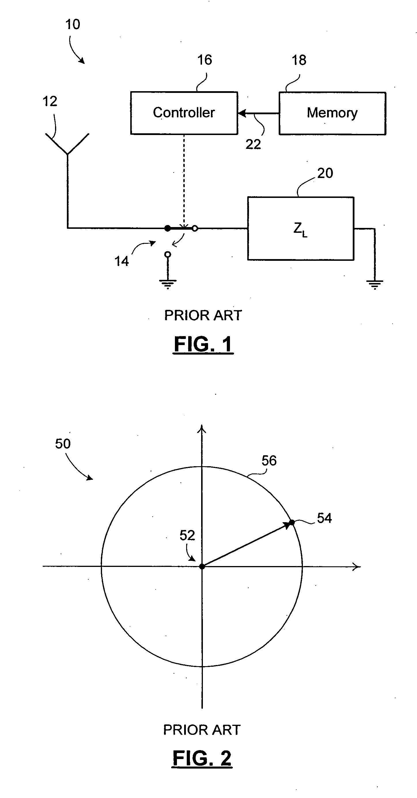
[0024] Reference is first made to FIG. 1, which diagrammatically shows a passive transponder 10 employing backscatter amplitude modulation. The passive transponder 10 includes an antenna 12, a switch 14, a controller 16, a memory 18, and a load impedance 20.

[0025] The switch 14 connects the antenna 12 either to ground or to the load impedance 20. The load impedance. 20 is connected between a terminal of the switch 14 and ground.

[0026] The switch 14 operates under control of the controller 16. The controller 16 receives a data signal 22 from the memory 18. The controller 16 operates the switch 14 in accordance with the data signal 22. The data signal 22 may, for example, include transponder information stored in the memory 18. The transponder information will depend on the application of the transponder 10. For example, in an ETC system the transponder information may include the transponder ID number, the last transaction time, the vehicle type, or other such information.

[0027] T...


PUM


Abstract

A radio frequency identification system having a passive backscatter transponder employing phase modulation. The transponder selectively couples its antenna to one of two or more impedances, wherein the impedances each produce a reflected signal when coupled to the antenna in the presence of a continuous RF wave from the reader. The reflected signals produced by the impedances are out-of-phase with each other. The transponder switches between impedances to encode transponder information into a reflected signal through phase shifts in the reflected signal. The reader detects the phase shifts in the reflected signal received at the reader to obtain the transponder information. The impedances are selected so as to produce reflected signals having a desired phase relationship or difference and having sufficient amplitude.

Description

FIELD OF THE INVENTION [0001] The present invention relates to radio frequency identification (RFID) systems, such as electronic toll collection (ETC) systems, and, in particular, to an improved backscatter transponder employing phase modulation in an RFID system. BACKGROUND OF THE INVENTION [0002] Radio frequency transponders and RFID tags are used in a variety of communications systems, especially systems in which a plurality of deployed devices, like vehicles, are outfitted with transponders that communicate with a set of readers connected to a central system. These types of distributed mobile communication systems may be employed for electronic toll collection, parking enforcement, valet services, fueling stations, traffic management, and a variety of other purposes. [0003] The transponders used in RFID systems are typically one of two types: active or passive. Active transponders include a power source that supplies electrical energy to the electronics of the transponder, there...

Claims


Application Information

Patent Timeline
IPC IPC(8): H04Q5/22
CPCG06K19/0723
Inventor ZHU, JEFFREY
Owner MARK IV INDS
Why Eureka
Eureka Blog
Learn More