3D imaging system

a 3d imaging and image processing technology, applied in the field of 3d imaging systems, can solve the problems of labour-intensive and inaccurate, not as reliable and accurate, and the automatic feature selection and matching algorithm is less accurate and reliabl

Active Publication Date: 2006-10-05
MACDONALD DETTWILER & ASSOC INC
View PDF12 Cites 358 Cited by
  • Summary
  • Abstract
  • Description
  • Claims
  • Application Information

AI Technical Summary

Benefits of technology

[0047] The present invention is very advantageous in that, unlike many existing 3D imaging systems, the stereo camera in the 3D imaging system does not require any external tracking devices or placing artificial markers to self-reference itself and register multiple views. Therefore this system can operate in an unknown environment or with unknown objects. The system can automatically create photo-realistic color 3D models quickly that allow measurement.

Problems solved by technology

The preferred case is when only existing features are used, however, in the prior art this is not as reliable and accurate as using artificial features (markers, beacons).
Feature selection and matching of observed objects is often performed manually, which is labour intensive and inaccurate.
Automatic feature selection and matching algorithms exist but are less accurate and reliable.
One sensor (especially with fixed optics and at one stand-off distance) cannot provide the resolution and depth of field required for the whole range of operations, e.g., room model and blood spatter analysis.
In the case of underground mine mapping, particularly, after generating 3D mine models using stereo cameras, it is difficult to register the models accurately with the mine map.
In the existing art, 3D modelling systems (both laser-based and camera-based) are not able to register to the mine map accurately themselves and require additional equipment.
On the other hand, total stations can locate themselves accurately but only provide very sparse 3D point data without photo-realism.
The limitation of this method is that it requires placing the registration pattern in the modeled environment and that the pattern always be visible in the second camera images.

Method used


Image

  • 3D imaging system
  • 3D imaging system
  • 3D imaging system

Examples


Embodiment Construction

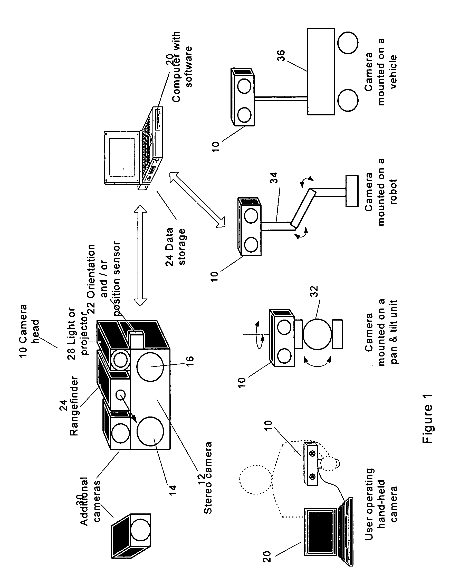
[0059] As used herein, the phrase “monocular camera” means an image recording device that projects an image of the observed scene through an optional lens onto a photosensitive element (e.g., CCD, CMOS) and equipped with means for transferring thus image to an image processing device (e.g., a computer).

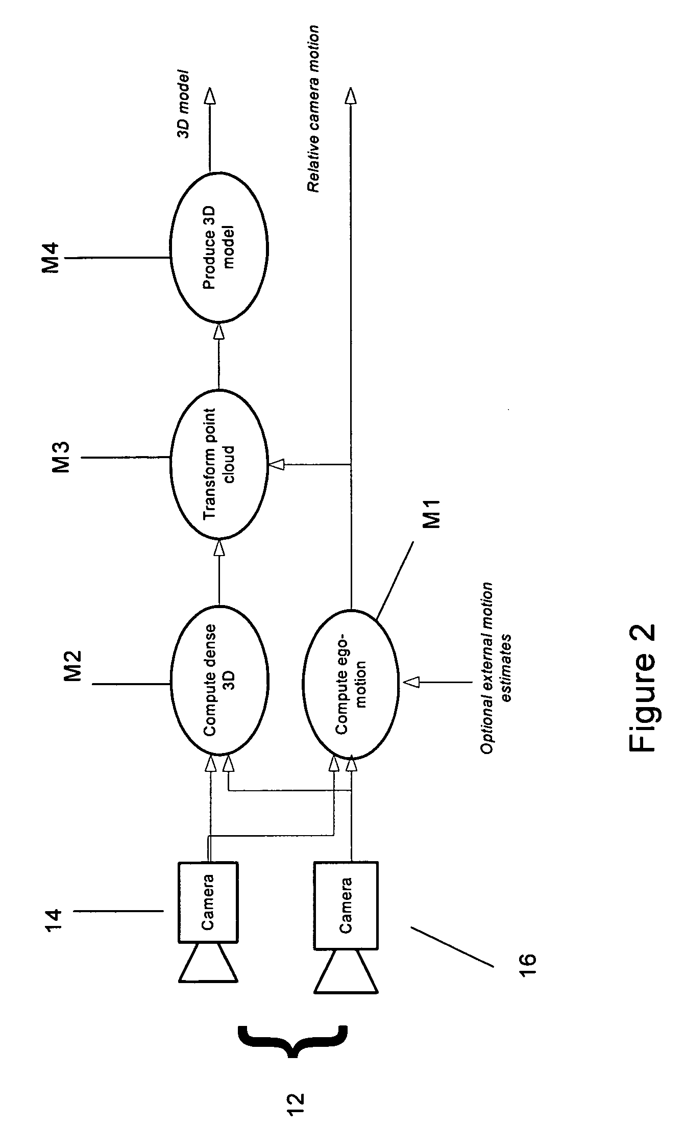
[0060] As used herein, the phrase “stereo camera” means a device that comprises two or more monocular cameras described above and observing approximately the same scene from a somewhat different point of view (the cameras may be combined in one enclosure).

[0061] As used herein, the phrase “auto-referencing” means an automatic method (algorithm) to establish correspondence (reference) between two or more data sets by detecting and matching common elements in the data sets.

[0062] As used herein, the phrase “tie-points” means distinctive local features that are matched between the stereo images taken at the same time or between stereo images taken at different time. Tie-points typical...


PUM


Abstract

The present invention provides a system (method and apparatus) for creating photorealistic 3D models of environments and/or objects from a plurality of stereo images obtained from a mobile stereo camera and optional monocular cameras. The cameras may be handheld, mounted on a mobile platform, manipulator or a positioning device. The system automatically detects and tracks features in image sequences and self-references the stereo camera in 6 degrees of freedom by matching the features to a database to track the camera motion, while building the database simultaneously. A motion estimate may be also provided from external sensors and fused with the motion computed from the images. Individual stereo pairs are processed to compute dense 3D data representing the scene and are transformed, using the estimated camera motion, into a common reference and fused together. The resulting 3D data is represented as point clouds, surfaces, or volumes. The present invention also provides a system (method and apparatus) for enhancing 3D models of environments or objects by registering information from additional sensors to improve model fidelity or to augment it with supplementary information by using a light pattern projector. The present invention also provides a system (method and apparatus) for generating photo-realistic 3D models of underground environments such as tunnels, mines, voids and caves, including automatic registration of the 3D models with pre-existing underground maps.

Description

CROSS REFERENCE TO RELATED U.S PATENT APPLICATIONS [0001] This patent application relates to U.S. utility patent application Ser. No. 60 / 651,639 filed on Feb. 11, 2005 entitled 3D IMAGING SYSTEM, filed in English, which is incorporated herein in its entirety by reference.FIELD OF THE INVENTION [0002] The present invention is related to an apparatus and a method for creating three-dimensional (3D) computer models (represented, for example, as point clouds, surfaces, or volumes) of environments and / or objects from a plurality of images from stereo and monocular cameras. BACKGROUND OF THE INVENTION [0003] Creation of photo-realistic and non photo-realistic three-dimensional (3D) calibrated models of observed scenes and objects has been an active research topic for many years and many commercial systems exist. Such 3D models can be used for visualization, virtual presence, operations planning and rehearsal, training and measurements. They are useful for many applications including plane...

Claims


Application Information

Patent Timeline
Patent Type & Authority Applications(United States)
IPC IPC(8): G06T17/00G06T17/05
CPCA61B5/113G01C11/06G06T7/0028G06T7/0071G06T2207/10021G06T7/2086G06T17/00G06T2200/08G06T7/0075G06T7/285G06T7/33G06T7/579G06T7/593
Inventor SE, SHUEN YAN STEPHENJASIOBEDZKI, PIOTRPARRY, DAVID OWENJAKOLA, ROY HENRY
Owner MACDONALD DETTWILER & ASSOC INC
Why Eureka
Try Eureka