Intravenous fluid warming system

Active Publication Date: 2006-10-05
VITAL SIGNS INC
View PDF24 Cites 17 Cited by
  • Summary
  • Abstract
  • Description
  • Claims
  • Application Information

AI Technical Summary

Benefits of technology

[0006] In one aspect of the present invention, a fluid warming system includes a pair of sliding covers that maintains a removable heat exchange body in place in heat exchange communication with a heater assembly. The heat exchange body is pressed in place by the covers in the closed position to guarantee good thermal conductivity. Fluid passing through the heat exchange body remains visi

Problems solved by technology

Because these walls are inefficient in transferring heat, heaters are exposed to both sides of the disposable set.
Both of these designs do not allow the user to see the fluid passing through the heat exchanger.
As these plastic walls are flexible, the pressure necessar

Method used


Image

  • Intravenous fluid warming system
  • Intravenous fluid warming system
  • Intravenous fluid warming system

Examples


Example

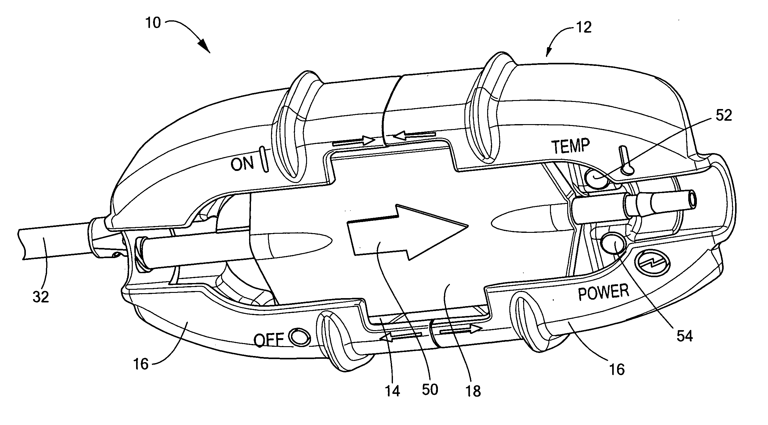
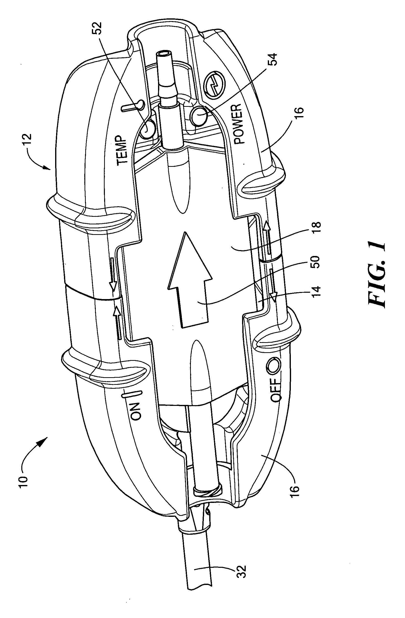
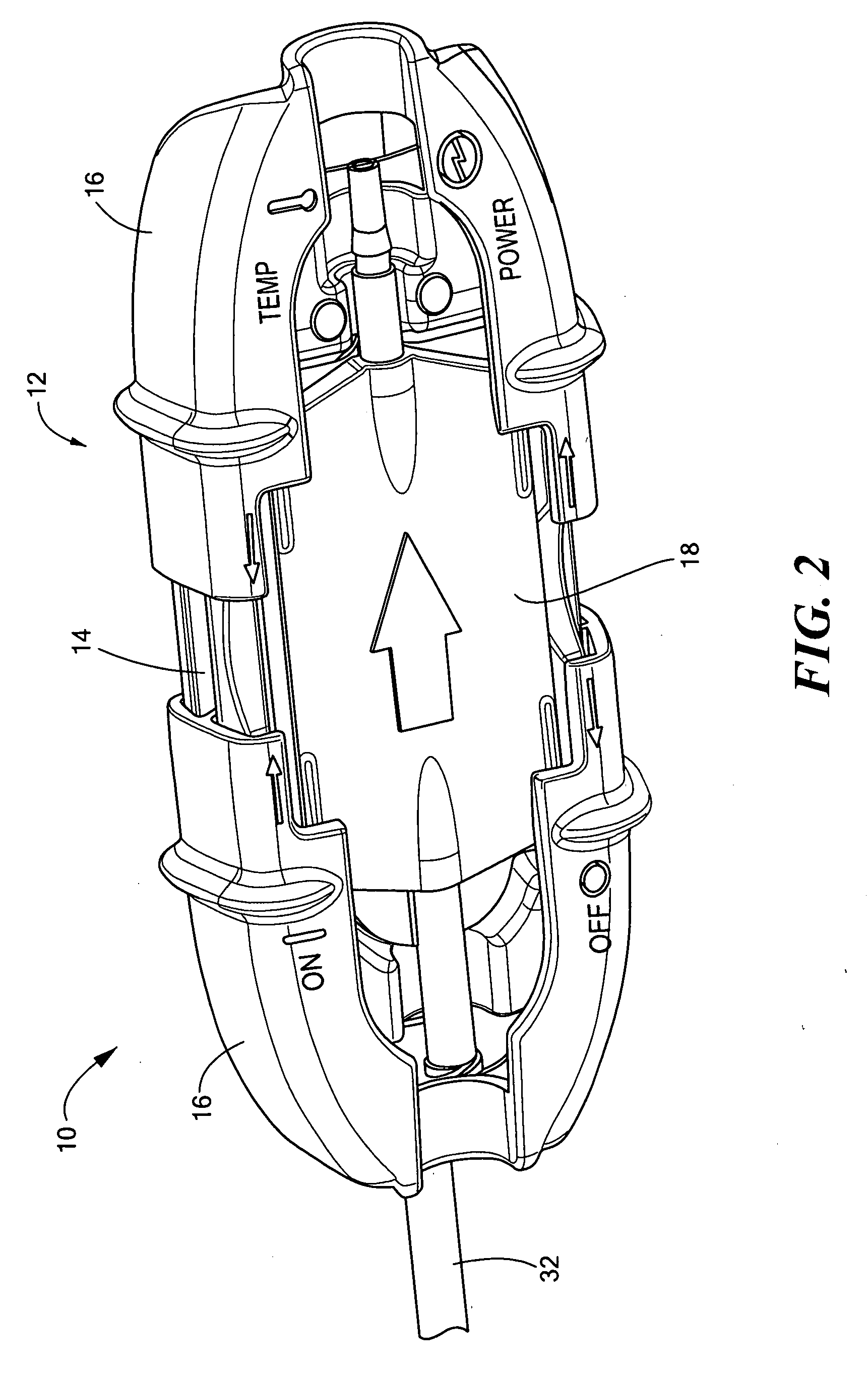
[0020] A fluid warming device 10 according to the present invention is illustrated in FIGS. 1-7. The fluid warming device includes a housing 12 having a main body 14 and two sliding covers 16. Within the housing, supported by the main body, are a removable heat exchange body 18 and a heater assembly 20. The sliding covers are independently slidable to a closed position in which they retain the removable heat exchange body in place, as described more fully below. The slidable covers are preferably identical.

[0021] The removable heat exchange body 18 and the heating assembly 20 are illustrated schematically in FIG. 7. The heat exchange body, also called a disposable or removable set, includes an input port 22 connectable to an IV tubing line from a source of IV fluid, which may include an infusion pump. The disposable set also includes an output port 24 connectable to a further IV tubing line to deliver the IV fluid to the patient. Within the disposable set, the IV fluid flows along ...


PUM


Abstract

A fluid warming device includes axially or longitudinally slidable covers that retain a removable heat exchange body in a housing in heat exchange communication with a heater assembly while allowing flow through the heat exchange body to be observed. In another aspect, a fluid warming system increases or decreases power to a heater assembly to adjust the fluid temperature to ensure that the fluid is at an appropriate temperature when it reaches the patient.

Description

CROSS REFERENCE TO RELATED APPLICATIONS [0001] This application claims the benefit under 35 U.S.C. § 119(e) of U.S. Provisional Application No. 60 / 663,857, filed on Mar. 21, 2005, the disclosure of which is incorporated by reference herein.STATEMENT REGARDING FEDERALLY SPONSORED RESEARCH OR DEVELOPMENT [0002] N / A BACKGROUND OF THE INVENTION [0003] Intravenous (IV) fluid warming devices are known that heat an IV fluid prior to introducing the fluid into a patient. Warmed IV fluids that are administered at very low flow rates can cool as they flow down the IV tubing to the patient. Often this heat loss is ignored. One prior art approach has been to simply heat the fluid to 41° C. to try to overcome the loss for all flow rates. [0004] In another aspect of fluid warming, most IV fluid warmers heat fluid through flexible plastic walls. Because these walls are inefficient in transferring heat, heaters are exposed to both sides of the disposable set. This requires inserting the disposable ...

Claims


Application Information

Patent Timeline
IPC IPC(8): A61F7/00
CPCA61M5/44A61M2205/583A61M2205/3653
Inventor CASSIDY, DAVID E.
Owner VITAL SIGNS INC
Why Eureka
Try Eureka