
Methods and apparatus for optical modulation amplitude measurement

a technology of optical modulation and measurement method, applied in the direction of optical apparatus testing, individual semiconductor device testing, instruments, etc., can solve the problems of not reporting a calibrated oma, no longer being able to determine whether an optical transceiver is an optical transceiver, and failing to assume the optical receiver. , to achieve the effect of reducing equipment costs, reducing costs, and speeding up testing tim

Inactive Publication Date: 2006-10-05
IBM CORP
View PDF7 Cites 13 Cited by
  • Summary
  • Abstract
  • Description
  • Claims
  • Application Information

AI Technical Summary

Benefits of technology

[0017] Accordingly, principles of the present invention provide techniques that enable measurement of OMA in a variety of settings and applications. For example, the inventive techniques may be used for field (e.g., customer location) measurement of OMA. Also, by way of further example, the inventive techniques may be used for optical component manufacturing measurements, which may lower costs through lower equipment costs and faster testing time.

Problems solved by technology

If the transceiver power levels were within specified limits, but the link continued to fail, then the problem was attributed to the optical cable plant.
If the link was delivering acceptable power levels and errors continued to occur, the failure was assumed to reside in the optical receiver.
This Standards change means that it is no longer possible to determine whether an optical transceiver is within specification simply by measuring the average optical power input to the receiver.
Such an approach is a ratio measurement of noise power to signal power and thus does not calibrate the photodetector to obtain a true OMA reading.
These methods and circuits do not and can not report a calibrated OMA.

Method used


Image

  • Methods and apparatus for optical modulation amplitude measurement
  • Methods and apparatus for optical modulation amplitude measurement
  • Methods and apparatus for optical modulation amplitude measurement

Examples


Embodiment Construction

[0025] While illustrative embodiments will be described below in the context of the FC standard, it is to be understood that principles of the invention are not limited to use with the FC standard and thus are more generally applicable for use with any suitable high data rate transport systems, e.g., FICON (Fibre Connection), 10 G Ethernet, etc. Furthermore, while principles of the invention may be suitable for use in fault determination, they are not limited to use therein. That is, OMA measurement techniques of the invention may be suitable for data communications standards conformance testing and verification, field applications, manufacturing applications, etc.

[0026] As will be described in illustrative detail below, principles of the invention provide a new, portable, low cost measurement tool which can directly determine OMA levels on a fiber optic link and correlate them with various standards.

[0027] In one embodiment, the portable OMA meter includes a calibrated photodetec...


PUM


Abstract

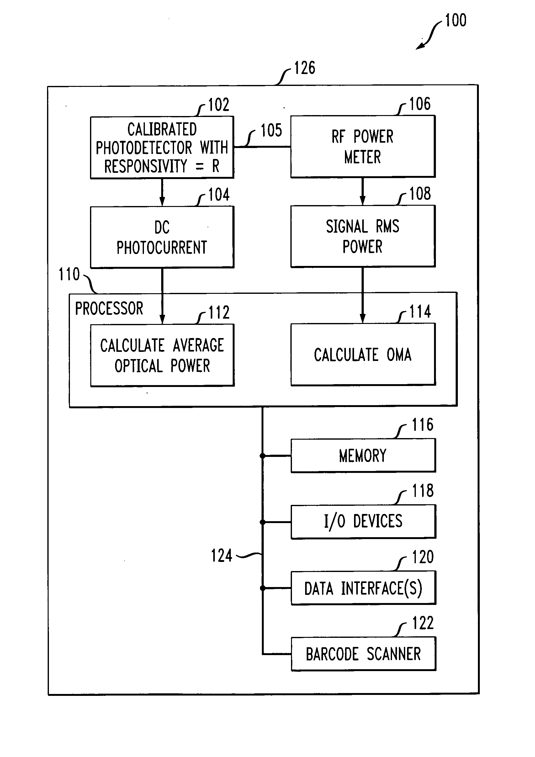
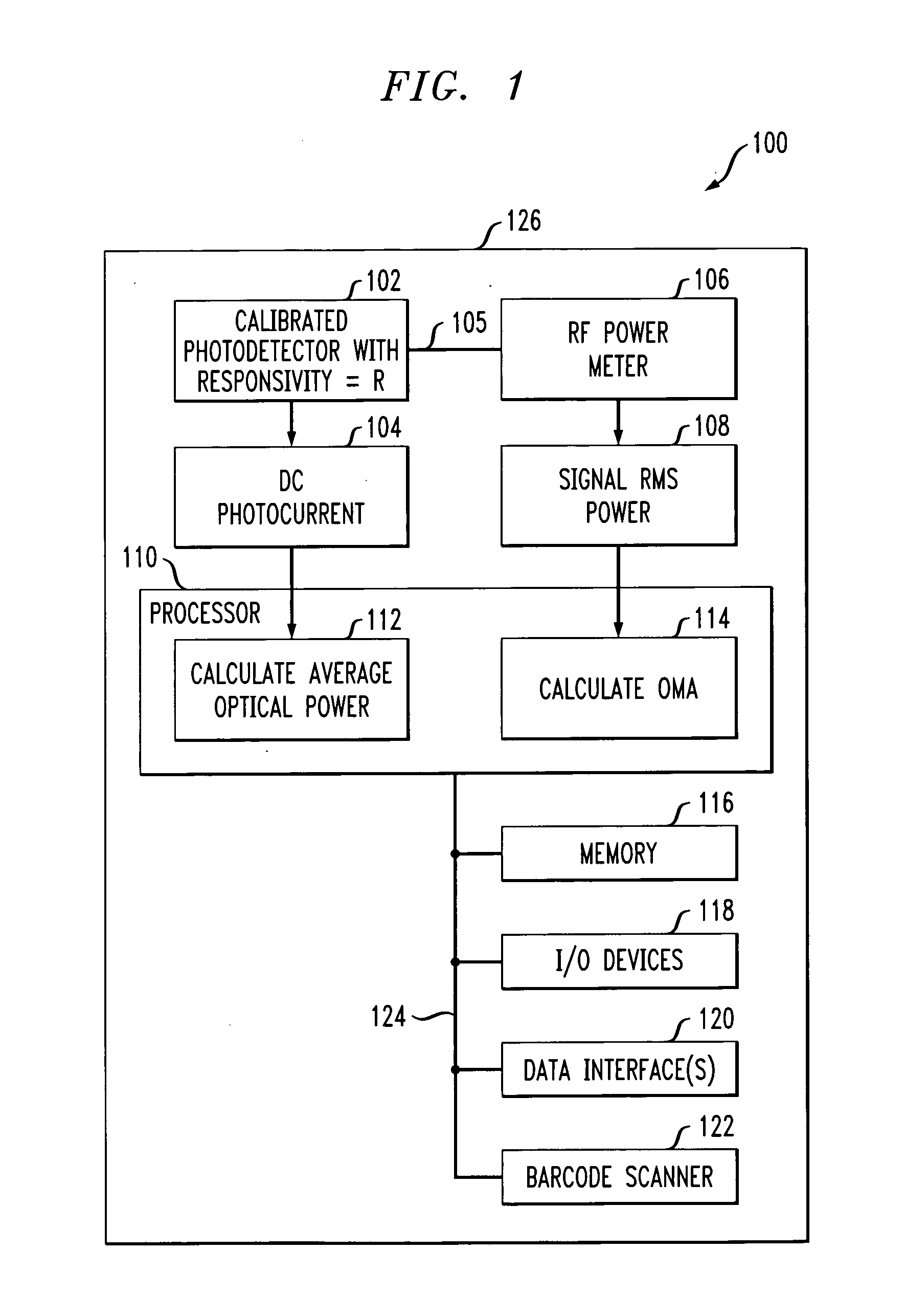
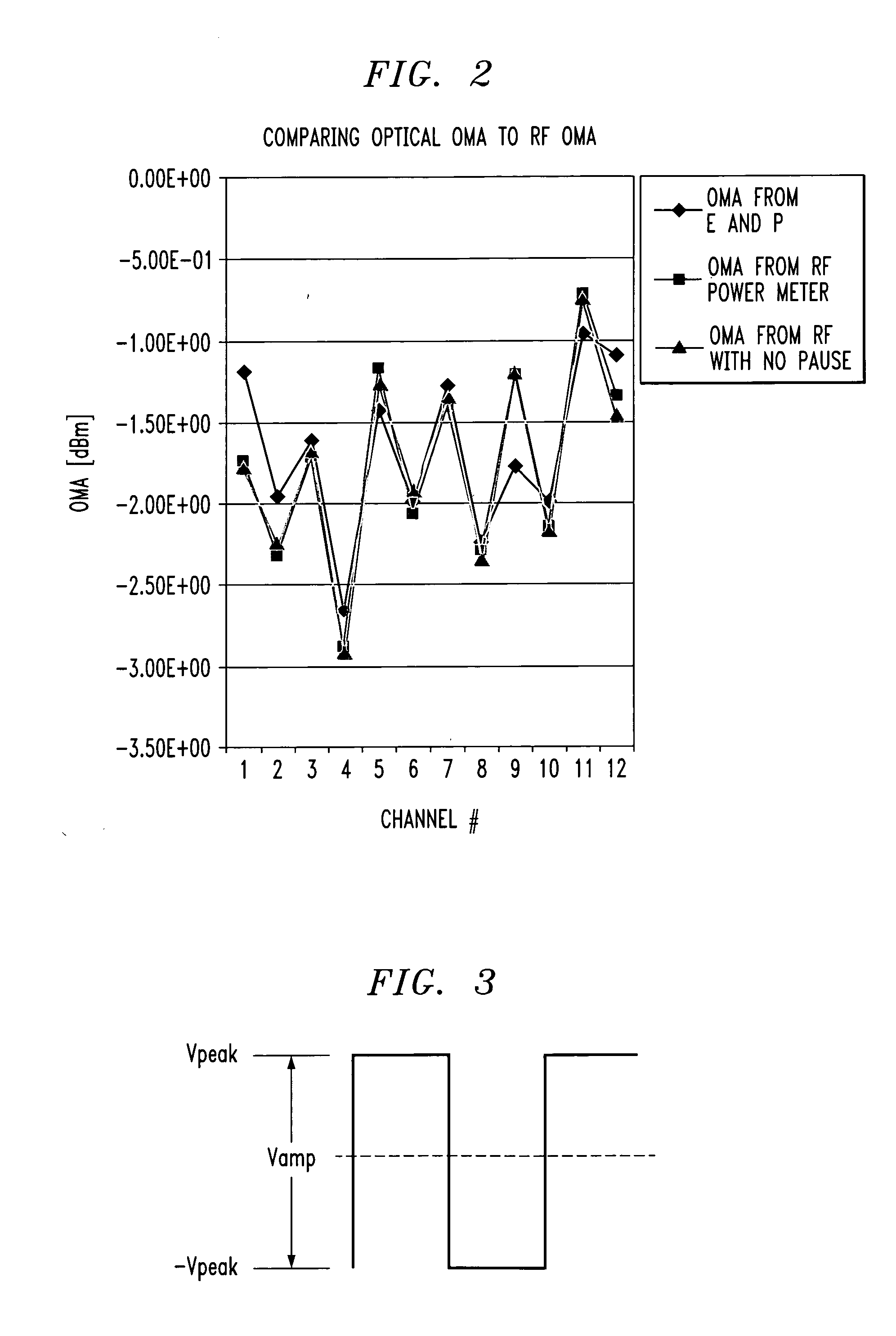
Techniques for measuring optical modulation amplitude (OMA) are disclosed. For example, a technique for measuring an OMA value associated with an input signal includes the following steps / operations. The input signal is applied to a photodetector, wherein the photodetector is calibrated to have a given responsivity value R, and further wherein the photodetector generates an output signal in response to the input signal. The output signal from the photodetector is applied to a radio frequency (RF) power meter, wherein the RF power meter measures the root mean squared (RMS) power value of the output signal received from the photodetector. The OMA value associated with the input signal is determined in response to the root mean squared (RMS) power value measured by the RF power meter. The OMA value may be determined as a function of a factor F derived from a relationship between an amplitude of a data signal and the RMS value of the data signal.

Description

FIELD OF THE INVENTION [0001] The present invention relates to optical network parameter measurement techniques and, more particularly, to techniques for measuring optical modulation amplitude. BACKGROUND OF THE INVENTION [0002] The Fibre Channel (FC) standards are an American National Standards Institute (ANSI) standards set that defines a common transport system for use with different protocols or applications. The initial core FC standard is identified as X.3230-1994-Fibre Channel Physical and Signaling Standard (FC-PH), the disclosure of which is incorporated by reference herein. [0003] Until recently, FC optical transceivers were specified with an acceptable range of optical receiver sensitivity and transmitter output measured in terms of average optical power at a minimum extinction ratio level. When an optical link failure occurred, fault determination procedures typically called for measurement of the average optical power at both transmit and receive ends of the link. If th...

Claims


Application Information

Patent Timeline
IPC IPC(8): H04B10/00G01R31/26
CPCG01M11/333G01M11/30
Inventor DECUSATIS, CASIMERKUCHTA, DANIEL M.SCHAUB, JEREMY DANIEL
Owner IBM CORP
Learn More