Steam turbine blade, steam turbine rotor, steam turbine with those blades and rotors, and power plant with the turbines

a technology of steam turbines and blades, which is applied in the direction of liquid fuel engines, vessel construction, marine propulsion, etc., can solve the problems of shortened fatigue life, increased fatigue load, and increased fatigue load, so as to suppress peak stress and suppress fretting fatigue

Active Publication Date: 2006-10-05
MITSUBISHI POWER LTD
View PDF15 Cites 16 Cited by
  • Summary
  • Abstract
  • Description
  • Claims
  • Application Information

AI Technical Summary

Benefits of technology

[0034] Further, according to the present invention, a steam turbine blade, a steam turbine rotor, a steam turbine with those blades and rotors, and a power plant with the turbines are obtained which can suppress peak stresses generated at the bottoms of the notches formed in the blade root and the blade groove, and which can also suppress fretting fatigue from being induced by contact between the peak stress generating areas and the areas opposed to the peak stress generating areas at the bottoms of the notches formed in the blade root and the blade groove.

Problems solved by technology

), when a substance contacts with the peak stress generating area under certain contact pressure, there is a possibility that fretting fatigue is induced and the number of cycles to failure is reduced to 1 / 10 or below in comparison with the case of simple fatigue.
This leads to a possibility that the fatigue life is shortened.

Method used


Image

  • Steam turbine blade, steam turbine rotor, steam turbine with those blades and rotors, and power plant with the turbines
  • Steam turbine blade, steam turbine rotor, steam turbine with those blades and rotors, and power plant with the turbines
  • Steam turbine blade, steam turbine rotor, steam turbine with those blades and rotors, and power plant with the turbines

Examples


first embodiment

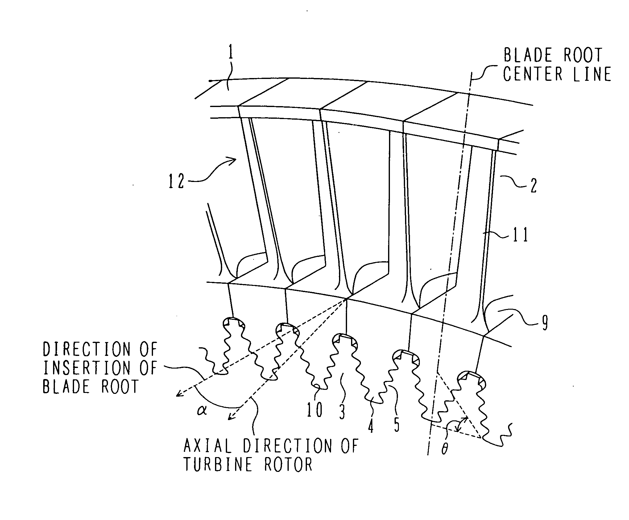
[0047]FIG. 1 is an oblique perspective view of steam turbine blades according to the present invention, the blades being attached to a turbine rotor. Each of the steam turbine blades in a first embodiment has an airfoil 2 and a fir-tree type blade root 4 which has an axis common to a blade groove (or a disc slot) 5 formed in an outer peripheral portion of a steam turbine rotor 3 and which is inserted in the blade groove 5 from one side in the axial direction of the turbine rotor for engagement between them. The blade root 4 is inserted in a direction forming a predetermined angle α larger than 0° relative to the axial direction of the turbine rotor. Hooks are formed in each of the fir-tree type blade root 4 and the blade groove 5 in plural stages in the radial direction of the turbine rotor. The steam turbine rotor 3 has a shaft and a wheel joined to the shaft. The wheel includes plural stages of slotted discs having slots into which the steam turbine blades are attached.

[0048] Mor...

second embodiment

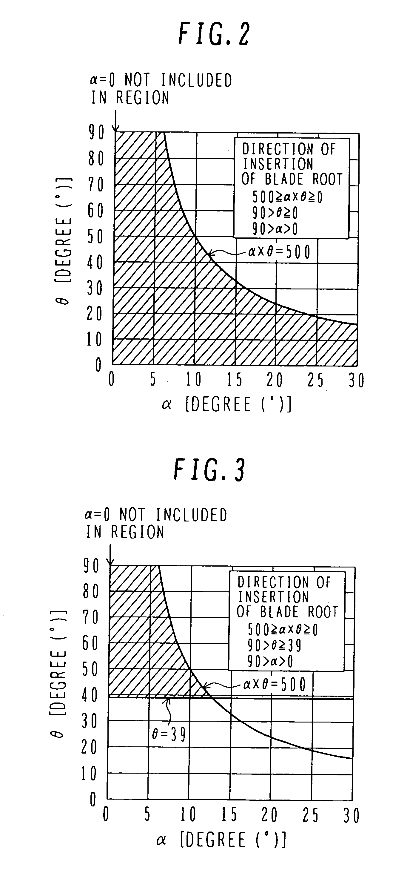
[0062] This second embodiment differs from the first embodiment in that a lower limit value for the range of the angle θ of the hook bearing surface is set to 39°, and the insert angle α of the blade root 4 and the angle θ of the hook bearing surface are satisfied by the following formulas 4, 5 and 6. The structure of the steam turbine blade in this second embodiment is the same as that in the first embodiment.

500≧α×θ≧0  (4)

90>θ≧39  (5)

90>α>0  (6)

[0063]FIG. 3 is a graph showing the relationship between the blade root insert angle α and the angle θ of the hook bearing surface. As shown in FIG. 3, the region specified by the formulas 4, 5 and 6 is a hatched region.

[0064] In this embodiment, by setting the angle θ of the hook bearing surface to be not smaller than 39°, even when any magnitude of centrifugal force acts on the turbine blade, the bearing surfaces of the hooks formed in the blade root 4 and the blade groove 5 cause relative slide between them such that the turbine bla...

third embodiment

[0067] In this embodiment, the range specified for the range of the angle θ of the hook bearing surface in any of the first and second embodiments is applied to only one among the plural stages of hooks 10, which is positioned at the innermost peripheral side in the radial direction of the turbine rotor 3. When the turbine root 4 of the axially-inserted inverted fir tree type is inserted in the direction forming the predetermined angle α relative to the axial direction of the turbine rotor 3, maximum peak stress is generated in many cases at the notch bottom under the hook 10 of the turbine groove 5, which is positioned at the innermost peripheral side in the radial direction of the turbine rotor 3. From such a practical point of view, the range specified for the value of the angle θ of the hook bearing surface is applied in this embodiment to only one among the plural stages of hooks 10, which is positioned at the innermost peripheral side in the radial direction of the turbine rot...


PUM


Abstract

A steam turbine blade in which the turbine blade has a blade root of the axially-inserted fir tree type and a larger number of turbine blades can be attached in a restricted outer peripheral region of a turbine rotor by arranging the blade root to be oriented in a direction forming a predetermined angle α larger than 0° relative to the axial direction of the turbine rotor. The steam turbing blade can suppress peak stresses generated at the bottoms of notches formed in the blade root and a blade groove and also suppress fretting fatigue from being induced by contact between peak stress generating areas and areas opposed to the peak stress generating areas at the notch bottoms. The steam turbine blade includes an airfoil, and a blade root attached to a turbine rotor and having plural stages of hooks in the radial direction of the turbine rotor.

Description

BACKGROUND OF THE INVENTION [0001] 1. Field of the Invention [0002] The present invention relates to a novel steam turbine blade and steam turbine rotor. The present invention also relates to a steam turbine with those blades and rotors, and a power plant with the turbines. [0003] 2. Description of the Related Art [0004]FIG. 9 is an oblique perspective view showing a state where known steam turbine blades are attached to a turbine rotor. Each of the turbine blades used in a steam turbine has a blade root 4 formed in a complex shape, and is attached to the turbine rotor by engaging the blade root 4 in a blade groove (or a disc slot in the turbine rotor) 5 having a shape complementary to that of the blade root 4. The blade root 4 has, for example, a structure of the axially-inserted fir tree type. A shroud 1 is provided at a top of the turbine blade for the purpose of reducing the steam leak loss. Hitherto, the shroud 1 has been prepared separately from an airfoil 2 having a blade pro...

Claims


Application Information

Patent Timeline
Patent Type & Authority Applications(United States)
IPC IPC(8): F01D5/30
CPCF01D5/3007F05D2250/314Y02T50/60
Inventor NOGAMI, SHUHEIYODA, HIDEO
Owner MITSUBISHI POWER LTD
Why Eureka
Try Eureka