Control device of internal combustion engine

a control device and internal combustion engine technology, applied in the direction of electric control, machines/engines, output power, etc., can solve the problems of increased cost, difficult to carry out excellent control (fuel efficiency, exhaust purification performance), complicated control of ignition, injection and throttle, etc., and achieve the effect of improving the homogeneity of fuel concentration (air-fuel ratio) in the combustion chamber

Inactive Publication Date: 2006-10-12
TOYOTA JIDOSHA KK
View PDF4 Cites 23 Cited by
  • Summary
  • Abstract
  • Description
  • Claims
  • Application Information

AI Technical Summary

Benefits of technology

[0016] According to the present invention, as the fuel is injected from the in-cylinder injector while the intake valve is open, the fuel injected from the in-c

Problems solved by technology

Accordingly, control of ignition, injection and throttle becomes complicated, and a control program adapted to each combustion manner is required.
In particular, in switching between combustion manners, such control should significantly be modified and it is difficult to carry out excellent control (fuel efficiency, exhaust purifying performance) at the time of transition.
In addition, as a three-way catalyst does not function in a stratified charge combustion region where lean combustion is conducted, a lean NOx catalyst should be used, which leads to increase in cost.
In such an engine, however, homogeneity is low in a region where engine speed is low and load is high, and to

Method used


Image

  • Control device of internal combustion engine
  • Control device of internal combustion engine
  • Control device of internal combustion engine

Examples


Embodiment Construction

[0031] An embodiment of the present invention will be described hereinafter with reference to the drawings. The same elements have the same reference characters allotted. Their label and function are also identical. Therefore, detailed description thereof will not be repeated.

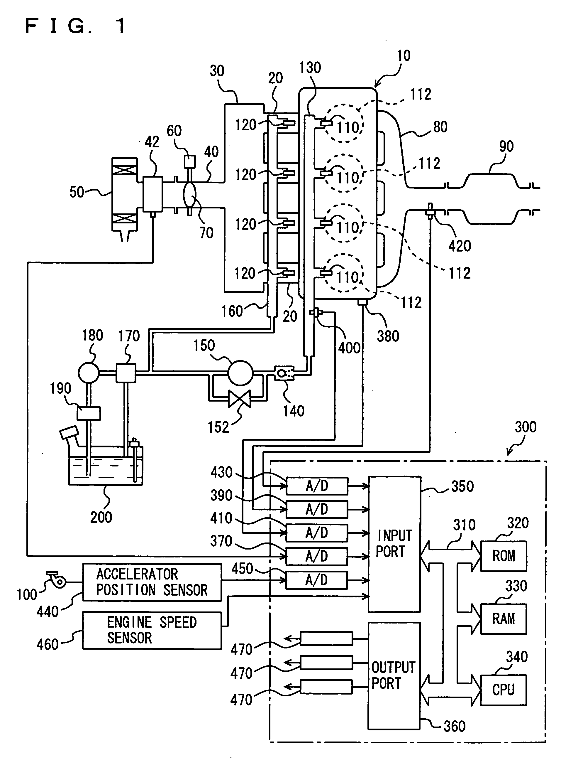
[0032]FIG. 1 schematically shows a configuration of an engine system controlled by an engine ECU (Electronic Control Unit) that is a control device of an internal combustion engine according to an embodiment of the present invention. Although an in-line 4-cylinder gasoline engine is shown in FIG. 1, application of the present invention is not restricted to the engine shown, and the engine may be a V-type 6-cylinder engine, a V-type 8-cylinder engine and an in-line 6-cylinder engine.

[0033] As shown in FIG. 1, an engine 10 includes four cylinders 112, which are connected via corresponding intake manifolds 20 to a common surge tank 30. Surge tank 30 is connected via an intake duct 40 to an air cleaner 50. In int...


PUM


Abstract

An engine ECU executes a program including the steps of: selecting a map for a warm state or a map for a cold state based on an engine coolant temperature after an engine is started and rapid catalyst warm-up ends; calculating DI ratio r; calculating when to inject fuel from an intake manifold injector as time in synchronization with air intake if a load factor is equal to or greater than a threshold value and fuel is injected from injectors at a ratio predetermined therebetween; and otherwise calculating when to inject fuel from the intake manifold injector as during a period in which an intake valve is closed.

Description

[0001] This nonprovisional application is based on Japanese Patent Application No. 2005-114715 filed with the Japan Patent Office on Apr. 12, 2005, the entire contents of which are hereby incorporated by reference. BACKGROUND OF THE INVENTION [0002] 1. Field of the Invention [0003] The present invention relates to a control device of an internal combustion engine that includes a first fuel injection mechanism (in-cylinder injector) for injecting fuel into a cylinder and a second fuel injection mechanism (intake manifold injector) for injecting fuel into an intake manifold or an intake port, and more particularly to a technique to determine when to inject fuel from the second fuel injection mechanism in homogenous combustion. [0004] 2. Description of the Background Art [0005] An internal combustion engine provided with an intake manifold injector for injecting fuel into an intake manifold of an internal combustion engine and an in-cylinder injector for constantly injecting fuel into ...

Claims


Application Information

Patent Timeline
IPC IPC(8): F02D41/30
CPCF02D41/024F02D41/047F02D41/16F02D41/22F02D41/2422Y02T10/44F02D41/3094F02D41/402F02M69/044F02M69/046F02D41/3029F02D2200/021F02D41/345Y02T10/40F02D41/40F02M69/04F02D41/30
Inventor SAITO, HARUHIKOTSUCHIYA, TOMIHISA
Owner TOYOTA JIDOSHA KK
Why Eureka
Try Eureka