Vessel grafting method

a grafting method and blood vessel technology, applied in the field of grafting methods for bypass surgery, can solve the problems of substantial morbidity and mortality risks, invasive procedure, and inability to accept all patients, and achieve the effect of convenient securement, improved graft and stent assembly, and convenient securemen

Inactive Publication Date: 2006-10-12
LIFESHIELD SCI
View PDF91 Cites 4 Cited by
  • Summary
  • Abstract
  • Description
  • Claims
  • Application Information

AI Technical Summary

Benefits of technology

[0008] Yet another embodiment of the present invention involves a graft and stent assembly which is securable to a sidewall of a blood vessel having an arteriotomy defined therein. The graft and stent assembly includes a graft having an end portion which is positionable within the blood vessel and substantially adjacent a portion of the sidewall of the blood vessel which substantially surrounds the arteriotomy. The graft and stent assembly further includes a stent positionable within the blood vessel and in contact with the end portion of the graft so as to secure the end portion of the graft between the sidewall of the blood vessel and the stent.
[0023] Yet another object of the present invention is to provide a graft and stent assembly which functions well after it is implanted in the body of a patient.

Problems solved by technology

Although conventional surgical bypass grafting is an accepted procedure, it presents substantial morbidity and mortality risks.
Also, not all patients are acceptable candidates for the above surgical procedure clue to advanced age and preexisting medical conditions.
Moreover, conventional surgical bypass grafting is an invasive procedure which may require extended hospitalization due to postoperative recovery.
In addition, the above surgical procedure may involve substantial financial costs to patients, hospitals and society in general.
Further, incisions made during the above surgical procedure may cause significant cosmetically unattractive scarring which is undesirable to many patients.

Method used


Image

  • Vessel grafting method
  • Vessel grafting method
  • Vessel grafting method

Examples


Embodiment Construction

[0069] For the purposes of promoting an understanding of the principles of the invention, reference will now be made to the embodiments and methods illustrated in the drawings and specific language will be used to describe the same. It will nevertheless be understood that no limitation of the scope of the invention is thereby intended, such alterations and further modifications in the illustrated devices and methods, and such further applications of the principles of the invention as illustrated therein being contemplated as would normally occur to one skilled in the art to which the invention relates.

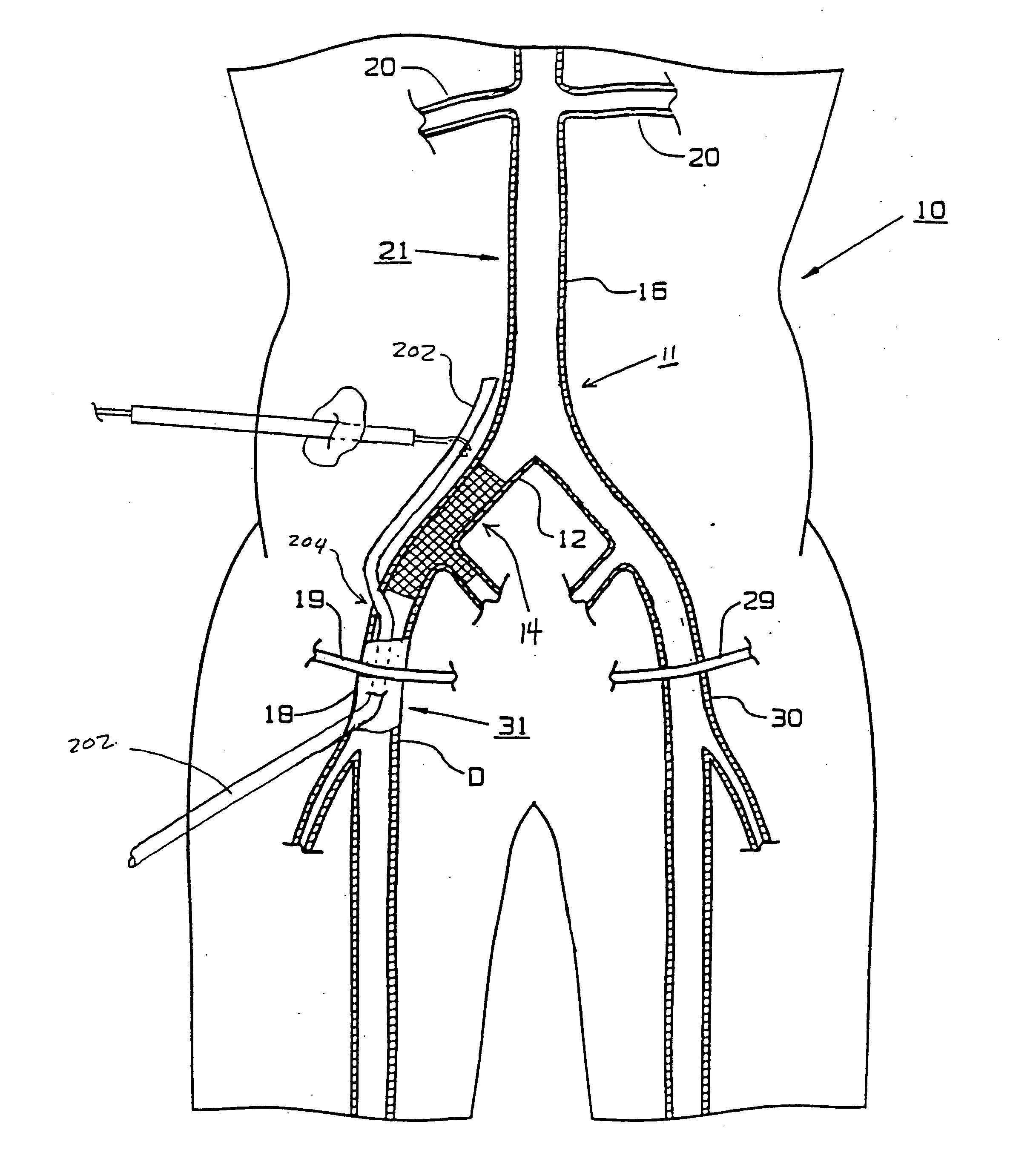
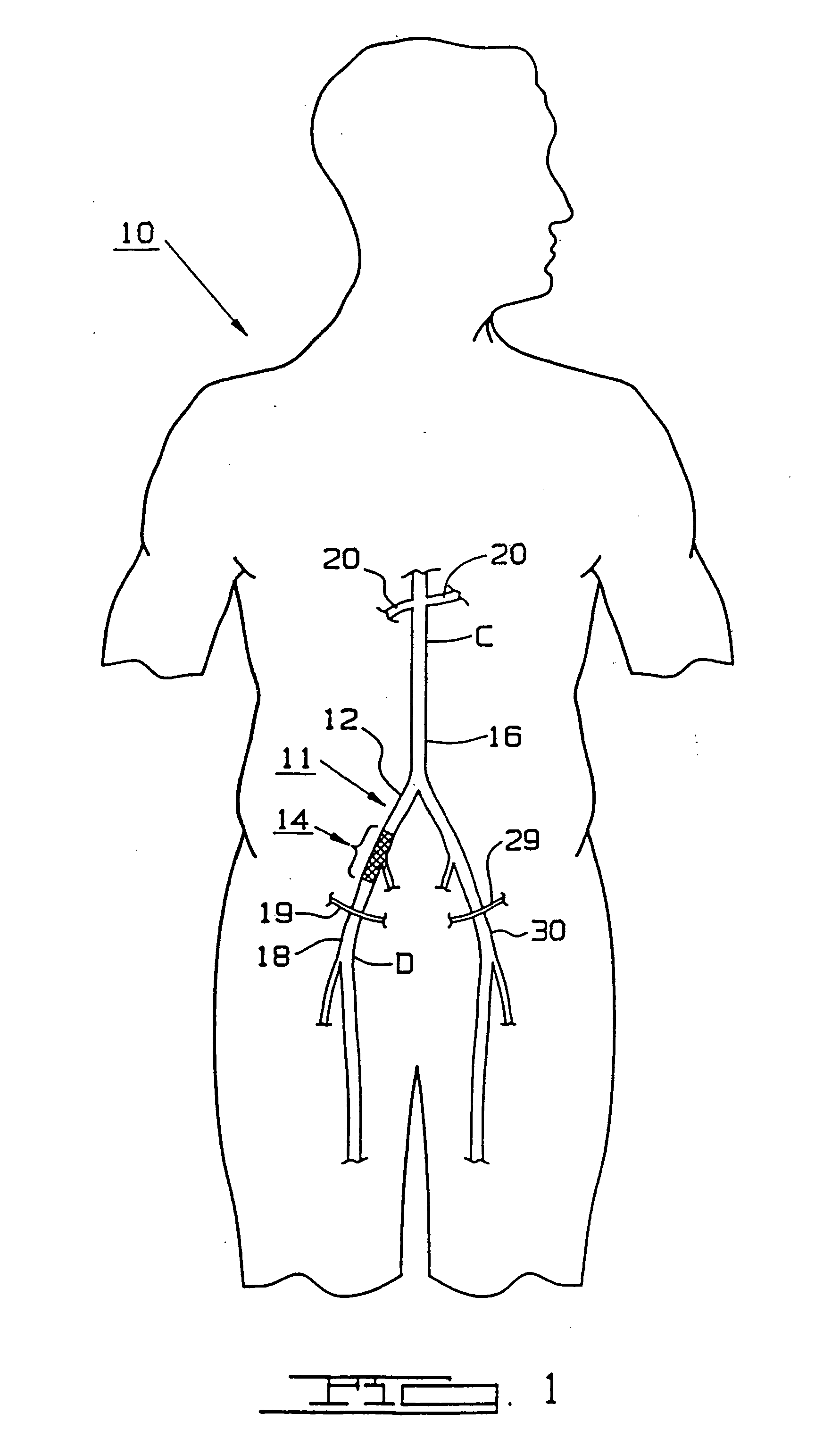
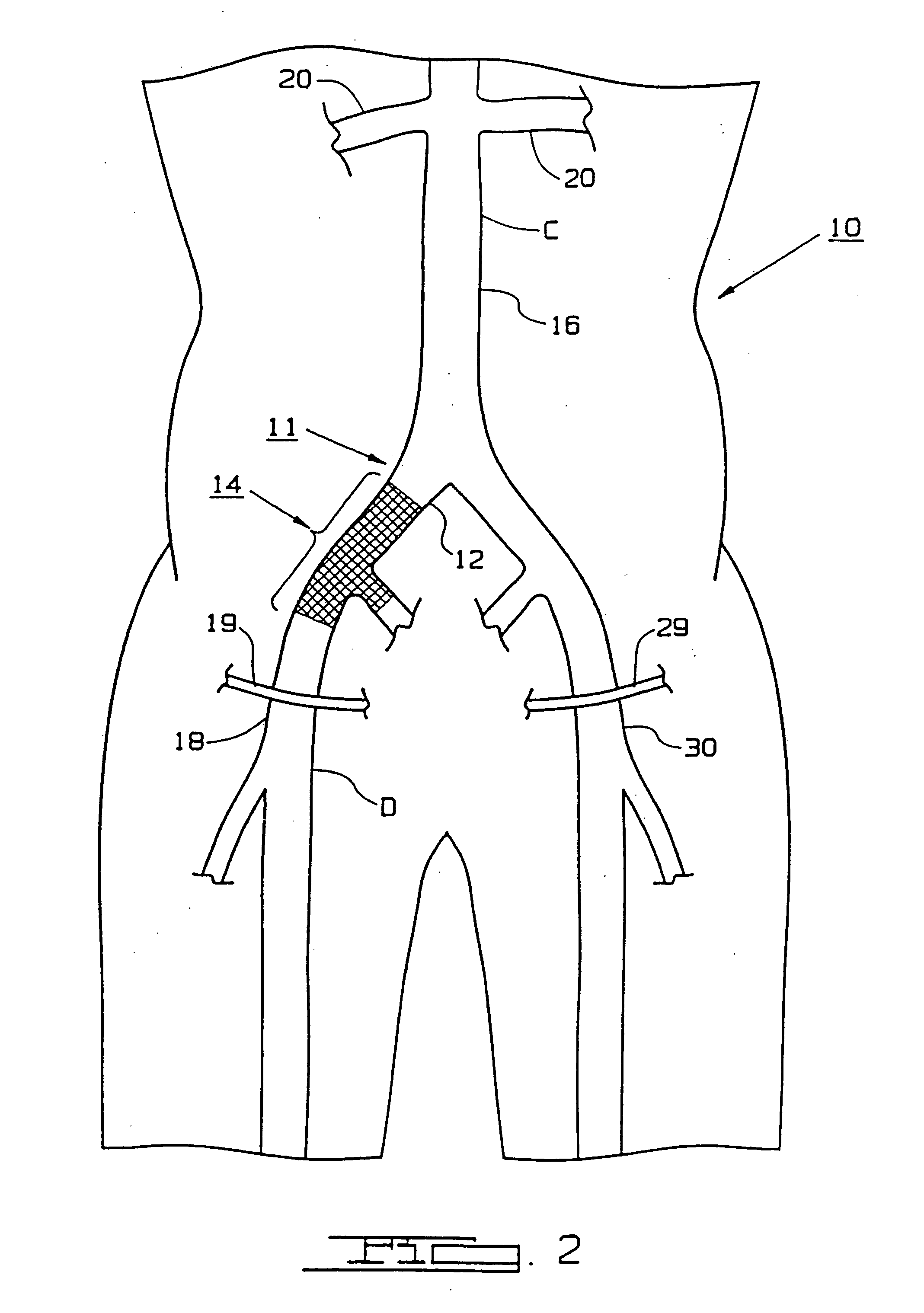
[0070] Referring now to the drawings, FIG. 1 shows a portion of a human body, generally designated by the reference numeral 10, with an artery, the common iliac artery 12, having an occluded segment, generally designated by the reference numeral 14. Human body 10 is further shown having other arteries, in particular, aorta 16, right common femoral artery 18, left common femoral artery...


PUM


Abstract

Minimally invasive techniques utilized in bypass grafting are disclosed. For instance, a method of implanting and end portion of a graft in the body of a patient during a bypass grafting procedure includes the steps of (i) advancing a medical instrument within a circulatory system of said body, (ii) guiding a distal end of said medical instrument out of said circulatory system through an opening defined in said circulatory system after said medical instrument advancing step, (iii) advancing said end portion of said graft within said medical instrument after said guiding step, and (iv) securing said end portion of said graft to a blood to vessel of said circulatory system after said end portion advancing step.

Description

RELATED CASES [0001] This application claims the benefit under 35 U.S.C. § 120 as a continuation of application Ser. No. 10 / 726,803, filed Dec. 2, 2003, which is a continuation of application Ser. No. 09 / 903,831, filed on Jul. 11, 2001, entitled “Bypass Grafting Method”, which is a continuation of application Ser. No. 09 / 475,789, filed Dec. 30, 1999, now U.S. Pat. No. 6,599,313, which is a continuation of application Ser. No. 09 / 111,062, filed Jul. 7, 1998, now abandoned, which is a continuation of application Ser. No. 09 / 090,598, filed Jun. 4, 1998, now U.S. Pat. No. 5,934,286, which is a continuation of application Ser. No. 09 / 073,336, filed May 5, 1998, now U.S. Pat. No. 5,979,455, which is a continuation of application Ser. No. 08 / 702,742, filed Aug. 23, 1996, now U.S. Pat. No. 5,749,375, which is a continuation of application Ser. No. 08 / 391,960, filed Feb. 21, 1995, now U.S. Pat. No. 5,571,167, which is a continuation of application Ser. No. 08 / 138,912, filed Oct. 18, 1993, no...

Claims


Application Information

Patent Timeline
Patent Type & Authority Applications(United States)
IPC IPC(8): A61F2/06A61B17/11A61F2/90
CPCA61B17/11A61B2017/1107A61F2/06A61F2/064A61F2/07A61F2/856A61F2002/075A61F2/954A61F2/958A61F2002/061A61F2002/065Y10S623/902Y10S623/903A61F2/90
Inventor MAGINOT, THOMAS J.
Owner LIFESHIELD SCI
Why Eureka
Try Eureka