
Lid dispenser

a dispenser and lid technology, applied in the field of dispensers for articles, can solve the problems of affecting the failure of the mechanism, and the failure of the dispensing device, so as to improve the cleanliness reduce or eliminate human contact, and ensure the effect of the dispensing operation

Inactive Publication Date: 2006-10-12
DAVIS MEGAN +1
View PDF2 Cites 11 Cited by
  • Summary
  • Abstract
  • Description
  • Claims
  • Application Information

AI Technical Summary

Benefits of technology

[0011] An object of the present invention is to not use gravity feed nor compression of the lids in an automatic dispenser to avoid failure caused by the jamming of the lids.
[0012] An object of the present invention is to raise, separate and deliver lids by means of a vacuum system to avoid jamming encountered with prior art gravity feed systems.
[0013] The present invention in a first embodiment is an automatic system for dispensing cup lids. This system employs a threaded shaft which is connected to an electric motor that is used to lift the lids from the bottom of a storage hopper where the lids are stacked prior to being dispensed. In this system, the lids ride on a platform which is supported by a bracket. The threaded shaft is passed through a mating threaded hole in the bracket. When the shaft is rotated by the electric motor, the platform and the lids rise to a level where the top most lid in a stack is in a position where it may be picked up by a vacuum system and dispensed to a user. Vacuum is used to lift and dispense an individual lid to the user, reducing or eliminating human contact with the lids before they are received by the user, thereby improving the cleanliness of the dispensing operation. In a second improved embodiment, a pick up system along with a delivery chute is added to the first embodiment to provide a more positive lid delivery system.

Problems solved by technology

The lids often have identical and at least partially interlocking configurations, causing them to stick together and jam as the dispenser attempts to dispense multiple lids simultaneously.
The gravity feed and translational movement of the bottom lid subject this device to the problems noted in connection with U.S. Pat. No. 4,319,441.
When the grips wear, the mechanism fails because it attempts to dispense multiple lids at once.
This device also uses gravity feed and a translational mechanical device operating on the bottom most lid and is subject to all the potential failures noted above for such systems.
This system increases this risk of failure when the bladder pressure is applied to the lids.

Method used


Image

  • Lid dispenser
  • Lid dispenser
  • Lid dispenser

Examples


first embodiment

[0033] this invention which describes the principal operating system is described in connection with FIG. 1-5.

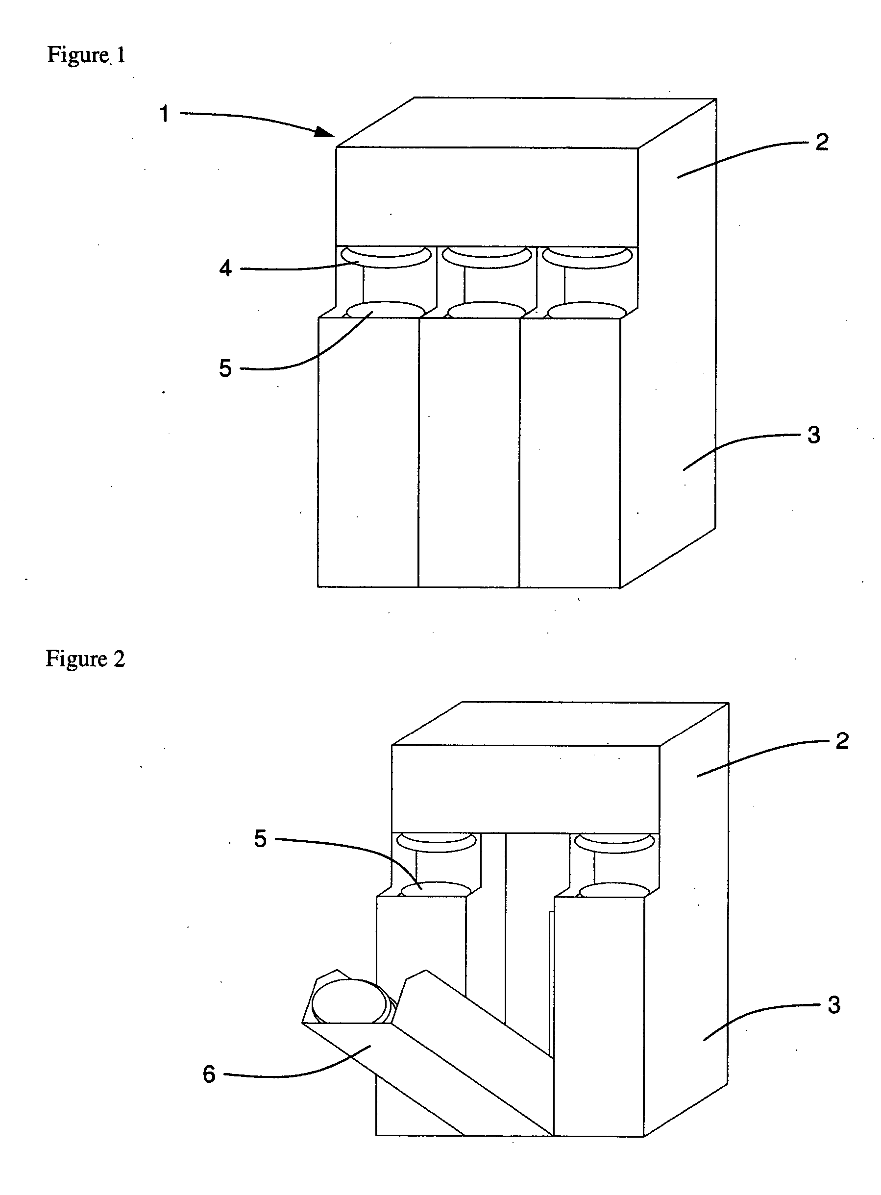
[0034]FIG. 1 is a front perceptive view of the lid dispenser shows the dispenser unit 1, to include an upper assembly 2, a lower assembly 3, a lid 4 ready for being dispensed, and a stack of stored lids 5. In the operation of this unit, a lid on top of stack 5 is lifted up by vacuum above the stack where it can be accessed by a user.

[0035]FIG. 2 is a front perspective view of the lid dispenser shown in FIG. 1 with a hopper 6 tipped forward to enable the hopper to be replenished with lids. Three hoppers are shown side by side in this Figure to enable a single dispenser unit to accommodate three different sized lids.

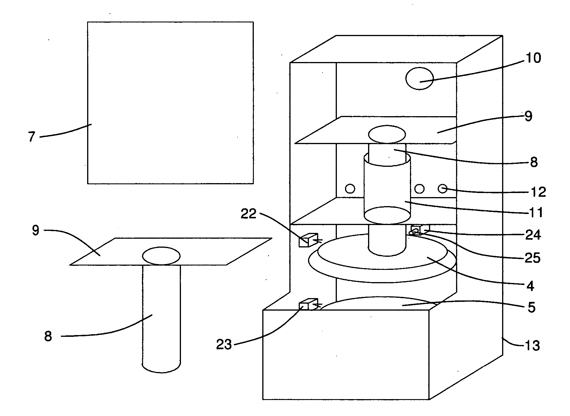
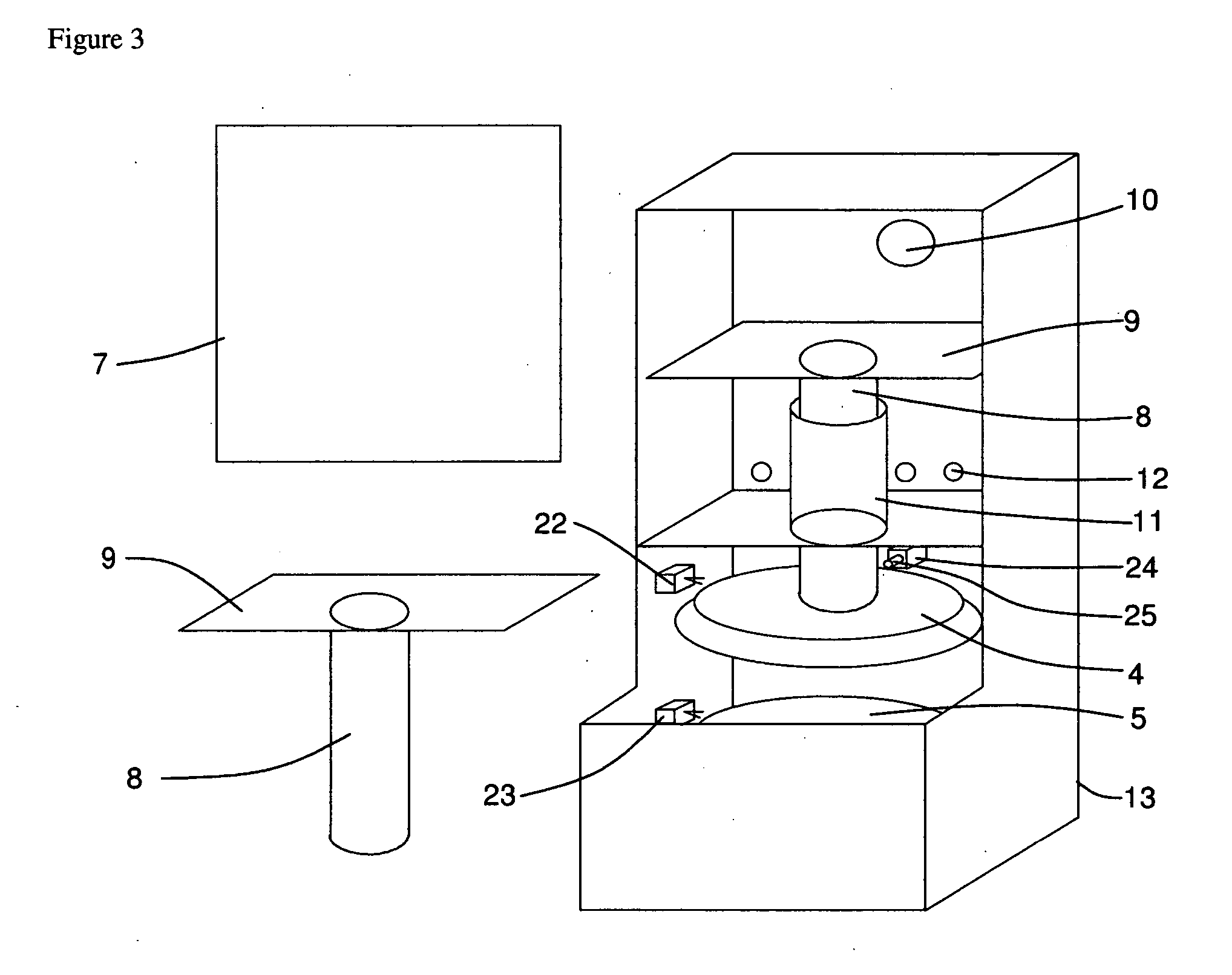
[0036]FIG. 3 is a front perspective view of the upper assembly of the lid dispenser with the front cover removed to reveal the operating components within the dispenser unit. In this view, the dispenser unit can be seen to include a dispenser lid sensor 22, a sli...

second embodiment

[0043] There are a number of alternatives which fall within the spirit and scope of the invention. In one arrangement, the top most lid after having been picked up by the sliding tube may be ejected by a device such as a solenoid upon its detection as having been picked up. An ejected lid sensor sends a signal to the control unit to pick up another lid. In a second arrangement, the lid may be left attached to the suction tube by way of the sliding tube for pick up by a person using the dispenser. An improved system for the delivery of the lid is described in the second embodiment below.

[0044] It is obvious that the present invention is not limited to cup lids, but is applicable to a wide variety of articles including plates and packets of condiments.


PUM


Abstract

Apparatus for dispensing lids and other articles such as plates, condiments, etc. comprising a threaded shaft powered by an electric motor which is used to raise a stack of items from the bottom of a storage hopper. A vacuum system, in a first embodiment comprised of a fan and a sliding tube, lifts the top most item from the stack, making it available to a user. A sensor at the top of the dispenser is used to detect the absence of an item in the dispensing position and again raises the stack of items, placing the top most item in position to be raised up by the vacuum system and again made ready for pick up by the user.

Description

BACKGROUND [0001] 1. Field [0002] The present invention relates to dispensers for articles and more particularly to dispensers for cup lids. [0003] 2. Prior Art [0004] The prior art is described in the following summary of five prior art patents: [0005] U.S. Pat. No. 4,319,441 illustrates an invention which performs multiple functions including lid dispensing that uses a carousel system wherein a cup is moved through several stations. However, this invention uses a circular translational motion to dispense lids which are stacked one above the other prior to being dispensed. This system uses gravity feed and removes the bottom most lid. The lids often have identical and at least partially interlocking configurations, causing them to stick together and jam as the dispenser attempts to dispense multiple lids simultaneously. [0006] U.S. Pat. No. 4,949,526 illustrates an automatic lid dispenser. The lids are stacked in a hopper. At the bottom of the hopper is a lid shuttle with an engage...

Claims


Application Information

Patent Timeline
Patent Type & Authority Applications(United States)
IPC IPC(8): B65G59/04
CPCB65B7/2807G07F11/14B65G59/026G07F11/1657
Inventor DAVIS, MEGANGARBUTT, MICHAEL
Owner DAVIS MEGAN
Learn More