
Video surveillance system and method with combined video and audio recognition

a video surveillance and audio recognition technology, applied in the field of surveillance systems and methods, can solve the problems of system simply not using rather precious audio information, and no useful information extracted from the audio input, so as to improve the accuracy of detection, reduce the time it takes, and improve efficiency

Inactive Publication Date: 2006-10-12
IBM CORP
View PDF3 Cites 79 Cited by
  • Summary
  • Abstract
  • Description
  • Claims
  • Application Information

AI Technical Summary

Benefits of technology

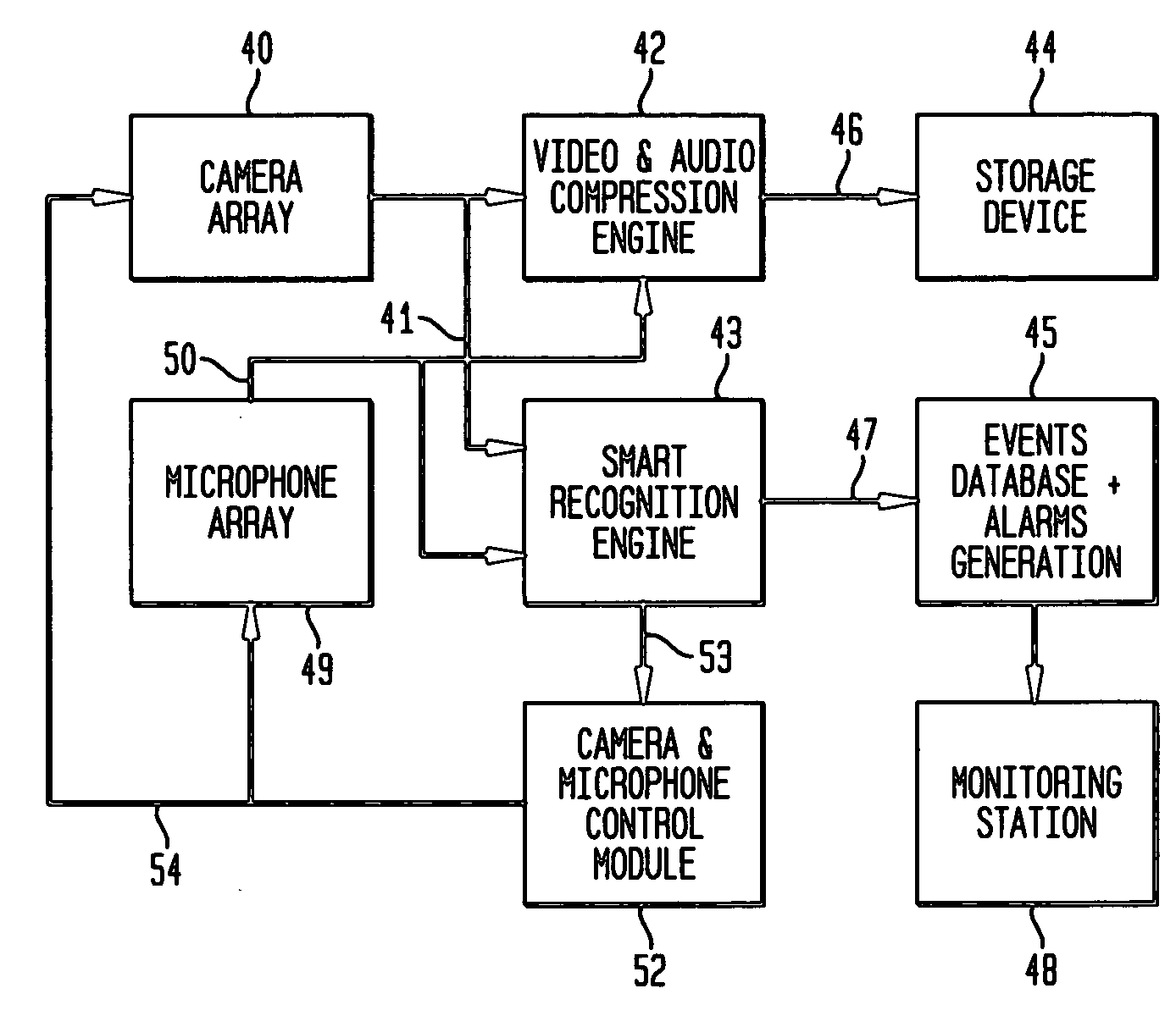
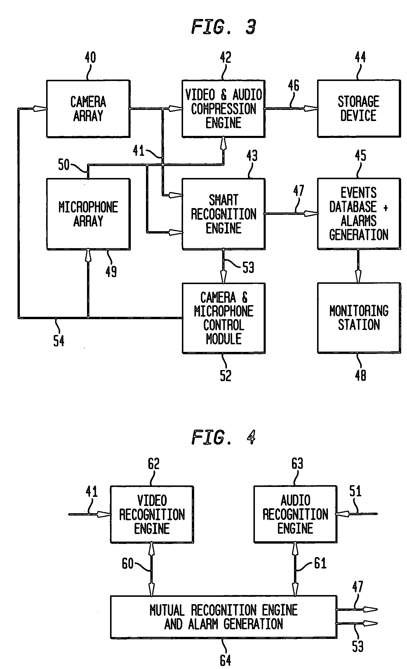
[0013] Using arrays of microphones placed in particular orientations, directions of sounds can be determined. Directional audio information may then be delivered to a camera control unit for directing a camera / cameras in the direction of interest. Further video / audio recognition may then be performed with better efficiency. Thus, for example, an explosion sound may be detected by audio recognition engine using an array of microphones in a monitored area. As a consequence, cameras will be directed into explosion direction and follow-on actions will take place in the video recognition engine—from alarming the monitoring station up to scene recognition / understanding. The instantaneous use of results from video and audio recognition to direct the further evaluation of recorded audio and video, and to direct improved recording of new video and audio inputs, advantageously improves the accuracy of the detection, reduces the time it takes to determine the nature of an alarm, and provides more information to a human operator evaluating the situation.

Problems solved by technology

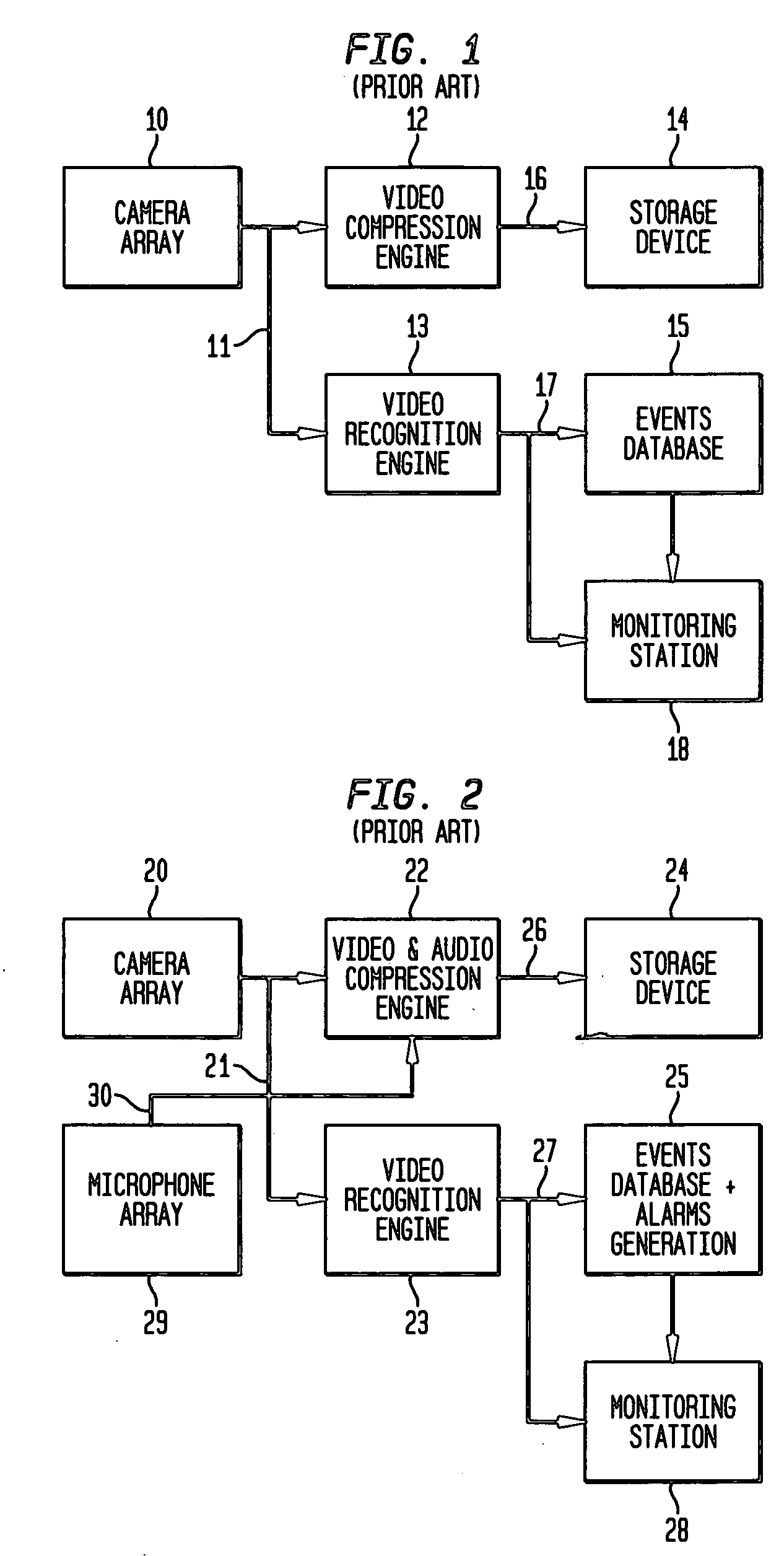
It is clear from the above description that there is no extraction of useful information from the audio inputs although such information is very often available in the audio signals obtained from at the monitored area.
Today's surveillance systems simply do not utilize rather precious audio information when analyzing video input.

Method used


Image

  • Video surveillance system and method with combined video and audio recognition
  • Video surveillance system and method with combined video and audio recognition
  • Video surveillance system and method with combined video and audio recognition

Examples


Embodiment Construction

[0025]FIG. 3 illustrates a Video Surveillance System with video and audio recognition according to the invention. As shown in FIG. 3 a camera array 40 comprising one or more still or video electronic cameras, e.g., CCD or CMOS cameras, either color or monochrome or having an equivalent combination of components that capture an area under surveillance feeds video signals into a digital video and audio compression engine 42 through a video communications link 41. Motion and operation of each camera device of the camera array 40 may be controlled by received control signals, e.g., under computer and / or software control. Moreover, operational parameters for each camera in camera array 40 including pan / tilt mirror, lens system, focus motor, pan motor, and tilt motor control are controlled by received control signals, as will be explained in greater detail herein. Prior to outputting the digital video signals, many signal processing techniques may be applied for reducing noise or providin...


PUM


Abstract

A novel video surveillance system is made up of video and audio compression engine, a storage device and, a video and audio recognition engine. The video recognition engine detects such events as face recognition, motion detection etc, whereas audio recognition engine detects voice and other sound signatures indicating a potential alarm situation, e.g., panic voices such as screaming and yelling, or sounds such as gun shots, explosions. Combined recognition of audio and video signals provides for higher true alarm generation and lower false alarms level of the surveillance system. Additionally, the audio recognition engine provides information for directing video cameras in the direction of interest allowing better capture of an interesting scene.

Description

BACKGROUND OF THE INVENTION [0001] 1. Field of the Invention [0002] The present invention generally relates to surveillance systems and methods for providing security, and, more particularly to a novel on-line (real-time) video and audio recognition system and process for surveillance systems. [0003] 2. Description of the Prior Art [0004] Conventional video surveillance systems typically do not include any functionality or provision for monitoring audio; i.e., surveillance systems do not include audio inputs at all. At best, typical video surveillance systems such as described in U.S. Pat. Nos. 6,724,421 and 6,175,382 provide simultaneous recording of visual and audio information. In both types of video surveillance systems described in these references, video data is being analyzed by smart surveillance engines and are compressed for digital storage. These engines implement various recognition algorithms such as face recognition, motion detection, panic detection, stabbing motion d...

Claims


Application Information

Patent Timeline
Patent Type & Authority Applications(United States)
IPC IPC(8): G02B27/10
CPCG08B13/194
Inventor KIENZLE, MARTIN G.SHEININ, VADIM
Owner IBM CORP
Learn More