Flexible conducting wire structure having light emitters

a flexible conducting wire and light-emitting technology, which is applied in the direction of semiconductor devices for light sources, lighting and heating apparatus, lighting support devices, etc., can solve the problems of wasting time and manpower, not providing economic scale, and not providing economic benefits, so as to reduce production costs

Inactive Publication Date: 2006-10-12
HUANG WEN CHUNG
View PDF7 Cites 4 Cited by
  • Summary
  • Abstract
  • Description
  • Claims
  • Application Information

AI Technical Summary

Benefits of technology

[0004] In order to conform to the usage requirements for the decorative light and reduce the prod...

Problems solved by technology

This kind of assembly wastes time and manpower, and does not provide the economic scale that the electronic-society looks forward to.
Therefore, it does not provide the economic benefits.
Besides, the poor assembly b...

Method used


Image

  • Flexible conducting wire structure having light emitters
  • Flexible conducting wire structure having light emitters
  • Flexible conducting wire structure having light emitters

Examples


Embodiment Construction

[0015] The above-mentioned features and advantages of this invention, and the manner of attaining them, will become more apparent and the invention will be better understood by reference to the following description of embodiments of the invention taken in conjunction with the drawings.

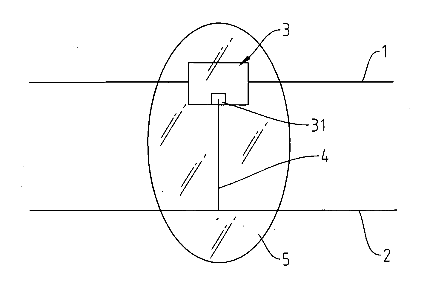
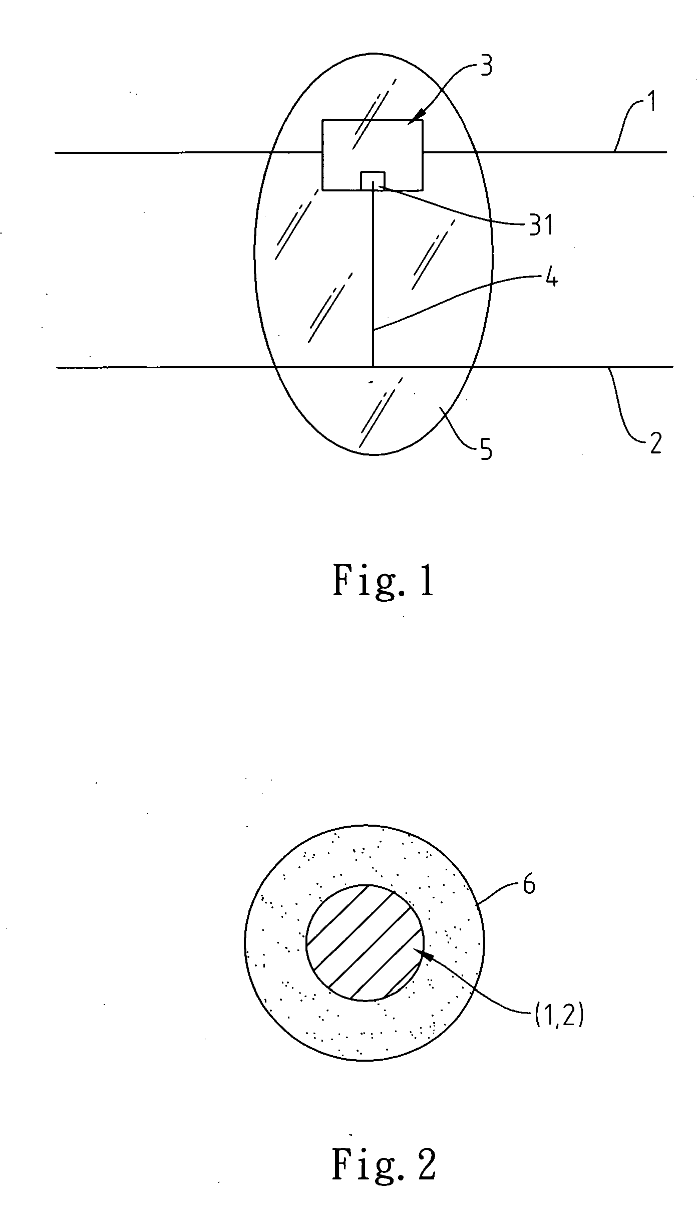
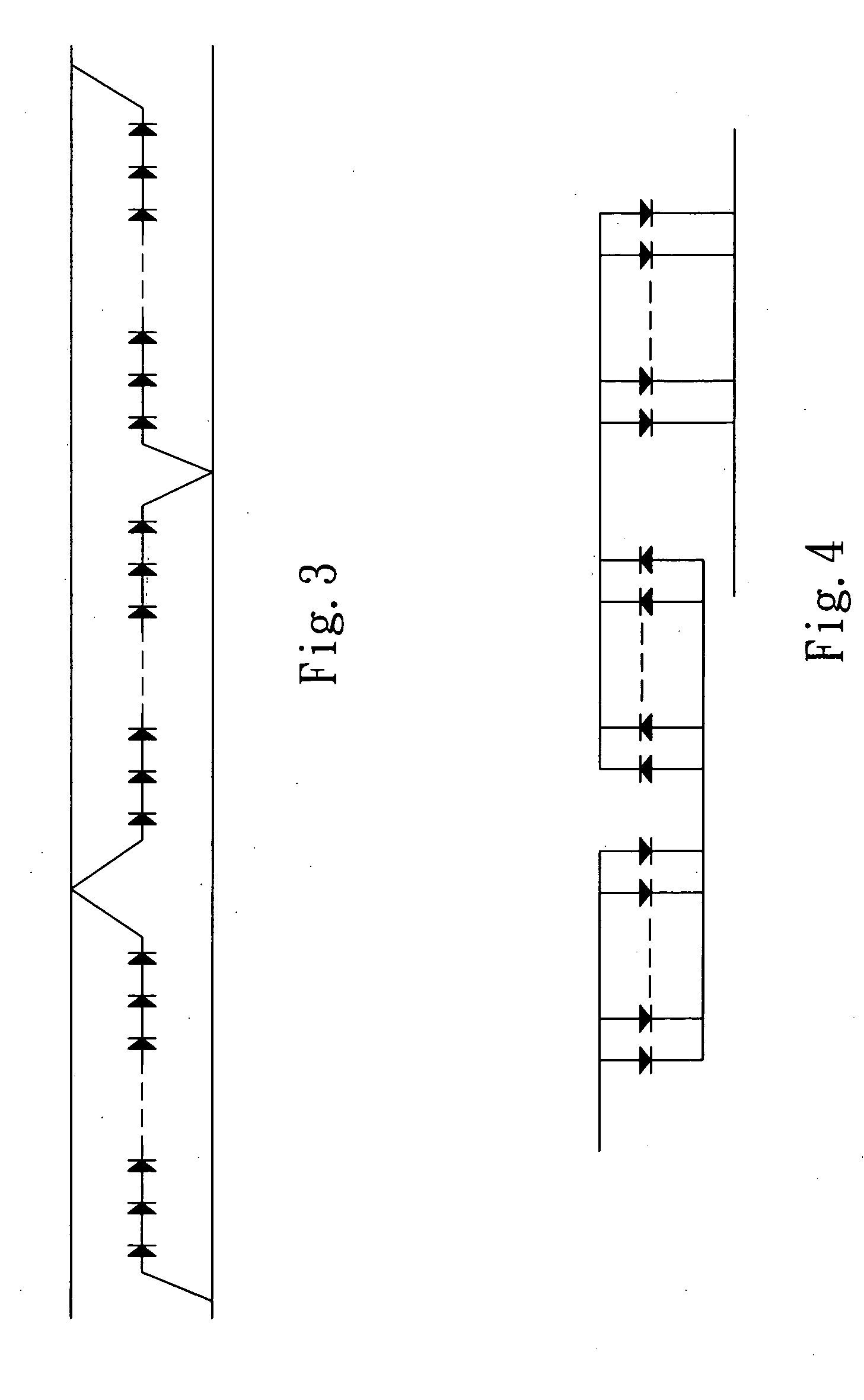
[0016] Referring to FIG. 1 and FIG. 2, a flexible conducting wire structure having light emitters of the present invention comprises two flexible conducting wires 1, 2 having different polarities and a plurality of chips 3 of a plurality of light emitting diodes (LEDs), wherein the flexible conducting wires 1, 2 are made of a high electrical conductivity material, for example, Au, Ag, Cu, etc. The chips 3 have second electrodes 31 mounted thereon, and the surfaces of the chips 3 form first electrodes. The chips of the LEDs are directly bonded on the surface of one of the flexible conducting wires, for example, the flexible conducting wire 1, by use of the surface mounting technology (SMT). Besides, t...


PUM


Abstract

A flexible conducting wire structure having light emitters is disclosed. Two flexible conducting wires with different polarities and a plurality of light emitting diodes having a plurality of chips having first electrodes and second electrodes are provided. The first electrodes of the light emitting diodes are electrically connected with one of the flexible conducting wires. The second electrodes of the light emitting diodes are electrically connected with the other of the flexible conducting wires via an extremely fine conducting wire. The chips of the light emitting diodes, the flexible conducting wires, and locations therebetween are covered with a layer of transparent adhesive for providing an transparent protective cap for the chips and the extremely fine conducting wire. The flexible conducting wires are covered with a layer of transparent insulating adhesive respectively for forming an insulating wire cover to avoid the occurrence of short circuit.

Description

FIELD OF THE INVENTION [0001] The present invention relates to a flexible conducting wire structure, and more particularly to a flexible conducting wire structure having light emitters. BACKGROUND OF THE INVENTION [0002] In the commonly seen decorative light that winds around the decorations, the light holders are mounted on two insulated conducting wires for obtaining electrical connection, and lamps or light emitting diodes are assembled on the light holders. When the external power is supplied to the insulated conducting wires, the light is emitted from the lamps or the light emitting diodes. [0003] On the basis of the above-mentioned description, the light emitters, for example, the lamps or the light emitting diodes, must be first assembled on the light holders so that the external voltage can excite the electrons to emit the light. This kind of assembly wastes time and manpower, and does not provide the economic scale that the electronic-society looks forward to. Therefore, it...

Claims


Application Information

Patent Timeline
IPC IPC(8): F21S4/00
CPCF21Y2101/02F21S4/001F21S4/10F21Y2115/10
Inventor HUANG, WEN-SHIN
Owner HUANG WEN CHUNG
Why Eureka
Try Eureka