Battery pack and method of producing the same

a battery pack and battery technology, applied in the field of batteries, can solve the problems of high facility cost, poor productivity, and insufficient reliability in contact state, and achieve the effects of preventing misuse of batteries, reliable electrical connection and fixation, and good productivity

Inactive Publication Date: 2006-10-12
PANASONIC CORP
View PDF7 Cites 12 Cited by
  • Summary
  • Abstract
  • Description
  • Claims
  • Application Information

AI Technical Summary

Benefits of technology

[0014] One of the external connection terminals should preferably have a connection leg extending from the terminal unit such as to overlap part of the outer surface of one end of the battery case and being connected to the outer surface of the battery case by welding, so that reliable electrical connection and fixation are achieved with good productivity by the welding of the connection leg of the external connection terminal with the outer surface of one end of the battery case. As the battery is welded with the terminal unit having the external connection terminals integrated with the insulating cover, the battery pack will not be disassembled to take out the battery and misuse of the battery is prevented. For the welding process, any of resistance welding, laser beam welding, electron beam welding or the like is suitably applied.
[0015] At least one gas outlet aperture should preferably be provided in the connection leg in a given location within a height range of from the position at which it is welded to the outer surface of the battery case and the position corresponding to the lower end of the terminal unit, or in the vicinity of the boundary between the battery case and the lower end of the terminal unit, so that a discharge path is formed for letting out gas generated in the event of abnormality in the battery to the outside of the battery pack, for enhanced safety of the battery pack.
[0016] The other one of the external connection terminals and the cap should preferably be connected to each other via a lead plate that is placed inside the terminal unit, so that they are connected easily and reliably, and that the connected part therebetween is protected by the terminal unit.
[0017] Furthermore, a PTC element or a temperature fuse may be provided in the lead plate, so as to obtain high safety features of the battery pack simply, compactly, and at low cost.
[0018] Further, it is preferable in terms of simplification and cost reduction of the battery pack, if one of the external connection terminals includes a layer having a different resistance from that of the external connection terminal, or a skin coating having a predetermined resistance on part of its surface, so that the external connection terminal has an identification terminal portion without having to use a special circuit substrate or a terminal substrate mounted with a resistance element.
[0019] Further, at least part of the terminal unit and the outer surface of the battery case may be covered by a film-like outer material. A simple and low cost outer configuration for the battery pack is thereby achieved, with only the terminal unit and the film-like outer material.

Problems solved by technology

Accordingly, there is a problem that sufficient reliability is hard to achieve in terms of the contact state between the external connection terminals of the battery pack 51 and the connection terminal in the battery pack accommodating space.
However, the mold forming has several drawbacks such as poor productivity, high facility cost, and a potential large profit loss due to defective products resulting from possible molding troubles.

Method used


Image

  • Battery pack and method of producing the same
  • Battery pack and method of producing the same
  • Battery pack and method of producing the same

Examples


Embodiment Construction

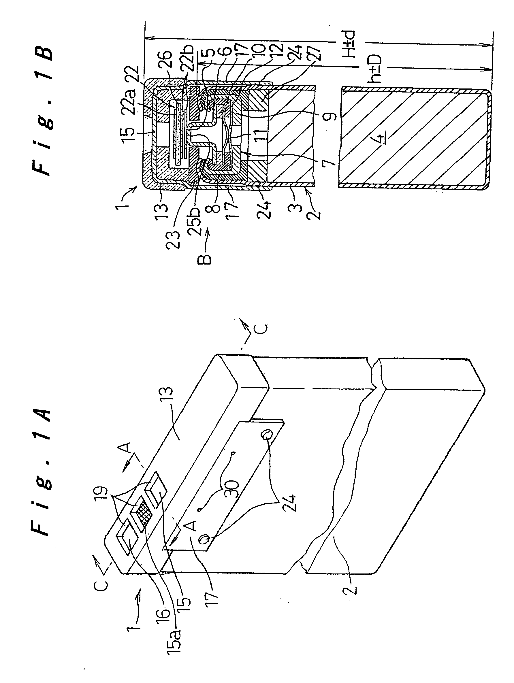
[0027] One embodiment of the battery pack and its manufacturing method of the present invention will be described below with reference to FIG. 1A to FIG. 6.

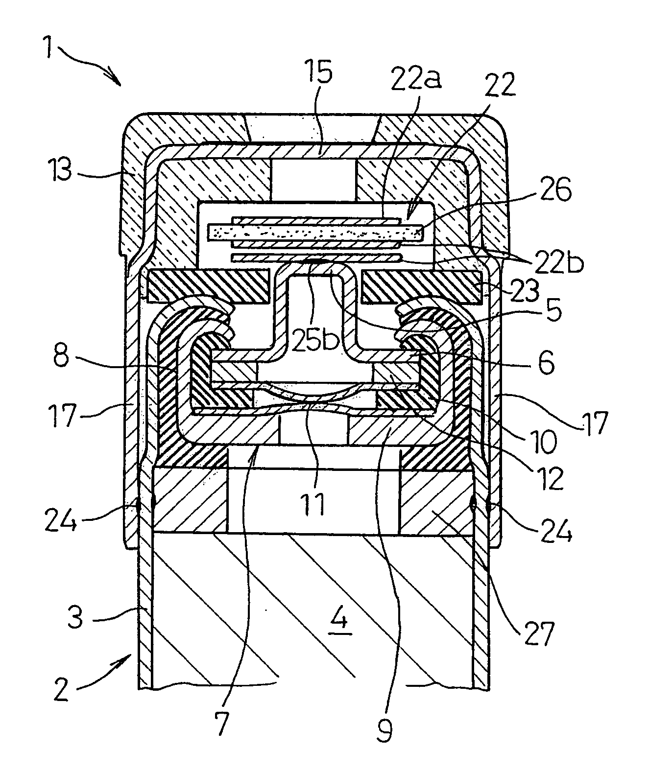
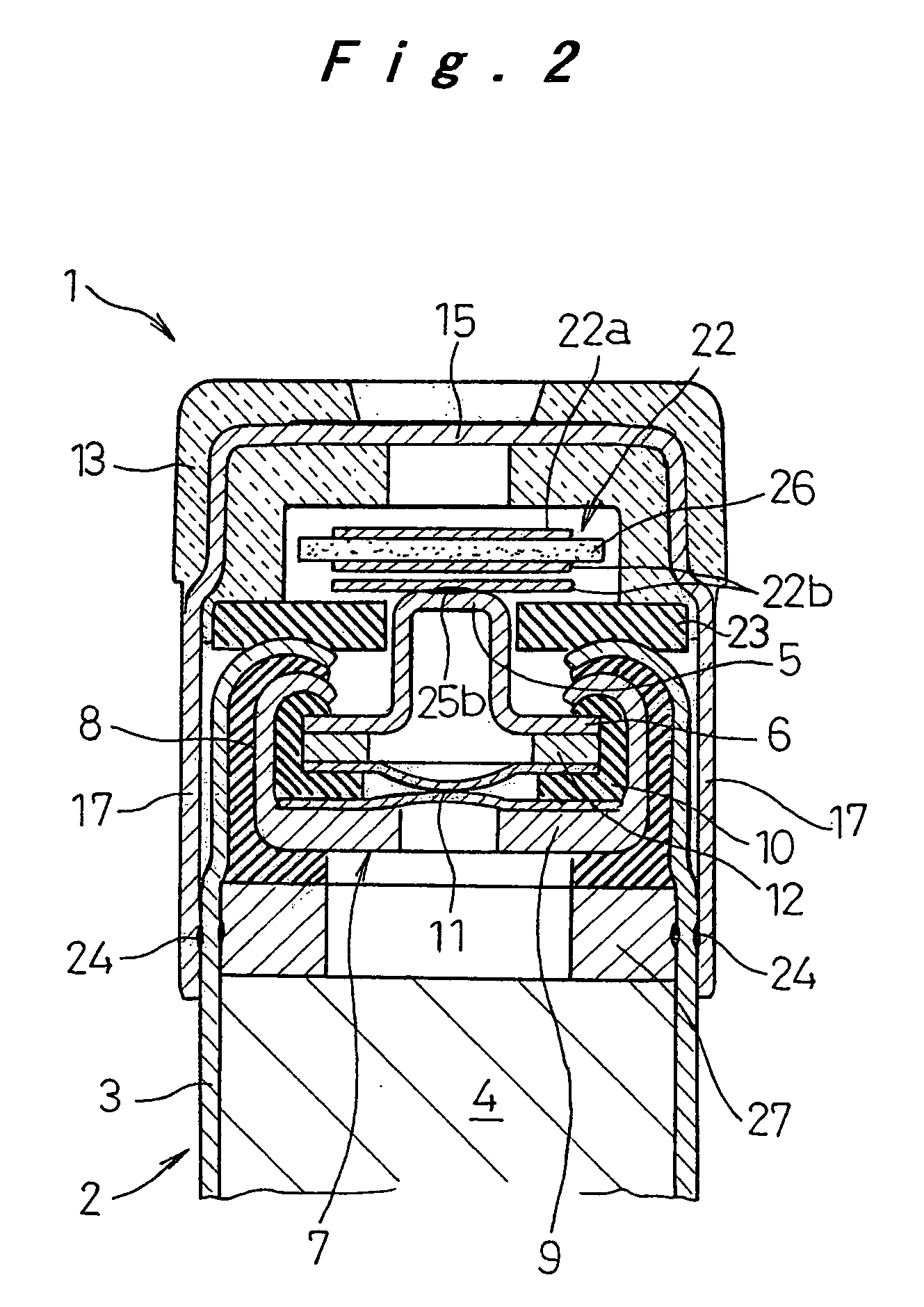
[0028] Referring to FIG. 1A and FIG. 1B, the flat prismatic battery pack 1 has a battery 2 structured as a lithium ion rechargeable battery. As shown in FIG. 2, the battery 2 is formed of elements for electromotive force 4 consisting of laminated positive and negative electrodes with separators interposed therebetween and liquid electrolyte, these elements being encased in a battery case 3. The open end of the battery case 3 is sealed by a sealing plate 7 having a cap 6 with a protruded part 5 and an insulating gasket 8, the cap 6 serving as a connection electrode of one polarity, and the battery case 3 serving as a connection electrode of the other polarity. The sealing plate 7 is formed of a filter 9 and a safety vent mechanism 11, a PTC element 12, and the cap 6 accommodated in the filter 9, with an inner gasket 10 being inte...


PUM

PropertyMeasurementUnit
polaritiesaaaaaaaaaa
resilientaaaaaaaaaa
dimensionaaaaaaaaaa

Abstract

A battery pack having a battery in which a battery case and a cap of a sealing plate sealing an open end of the battery case serve as connection electrodes of opposite polarities, a terminal unit including external connection terminals respectively connected to these connection electrodes and an insulating cover integrally formed therewith, the terminal unit covering at least one end of the battery case, and a resilient member interposed between one end of the battery case and the terminal unit in a compressed state. In the manufacturing method of this battery pack, the dimension between the terminal unit and the other end of the battery case is controlled when fixing the terminal unit with the battery case. The battery pack thus has a simple and low cost configuration and yet exhibits high reliability in terms of the connection state of the external connection terminals when set in a portable electronic device.

Description

TECHNICAL FIELD [0001] The present invention relates to a battery pack suitably used as a battery power source of portable electronic devices or the like, and more particularly to a battery pack having an enhanced external connectivity, and to its manufacturing method. BACKGROUND ART [0002] With the remarkable development of small, thin, and high-functionality portable electronic devices of the recent years, there is a growing demand for small, thin, and high-capacity batteries as the power source of these devices. Generally, lithium batteries can be structured small with a high capacity. In particular, flat prismatic lithium ion rechargeable batteries are suitable for the devices to be made thinner, and therefore they have been increasingly used as the rechargeable battery for portable electronic devices such as mobile phones. [0003] There is known a battery pack used as a power source of various devices, including a battery and a circuit substrate provided with an overcurrent limi...

Claims


Application Information

Patent Timeline
Patent Type & Authority Applications(United States)
IPC IPC(8): H01M2/06H01M2/08H01M2/12H01M2/04H01M2/10H01M2/30H01M6/50
CPCH01M2/0426H01M2/10Y10T29/4911H01M2200/106H01M2/1022Y02E60/10H01M50/169H01M50/20H01M50/543
Inventor EBI, RYUICHIROMASUMOTO, KENJINKITAGAWA, TOSHIHARU
Owner PANASONIC CORP
Why Eureka
Try Eureka