Aortic valve repair

a technology for repairing aortic valves and valves, applied in the field of aortic valve repair, can solve the problems of reducing the functional area of the valve, reducing the efficiency of the valve, and progressive immobility of the valve tissue, and achieve the effect of reducing restlessness and increasing efficacy

Active Publication Date: 2006-10-12
TWELVE
View PDF99 Cites 136 Cited by
  • Summary
  • Abstract
  • Description
  • Claims
  • Application Information

AI Technical Summary

Benefits of technology

[0021] Various energy sources may be utilized to effect the treatment of the present invention, including RF, ultrasonic energy in various therapeutic ranges, and mechanical (non-ultrasound) energy. The distal tips of the RF, ultrasonic treatment catheters, and mechanical treatment catheters of the present invention may have a variety of distal tip configurations, and be may be used in a variety of treatment patterns, and to target specific locations within the valve.
[0

Problems solved by technology

In developing countries, rheumatic fever results in thickening and progressive immobility of the valve tissues.
The presence and progression of this disease leads to a decreased functional area of the valve and dramatically reduced cardiac output.
Devices and techniques have suffered from only a modest ability to increase valve cross-sectional area, however.
Toward this end, other techniques such as direct surgical ultrasonic debridement of calcium deposits have had some success, but required an open surgical incision, thereby increasing the risk to the patient.
Although bal

Method used


Image

  • Aortic valve repair
  • Aortic valve repair
  • Aortic valve repair

Examples


Embodiment Construction

Treatment Catheter Design—General

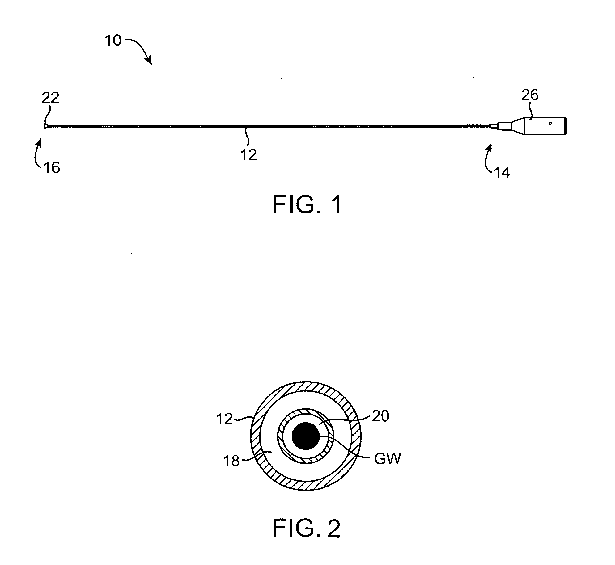
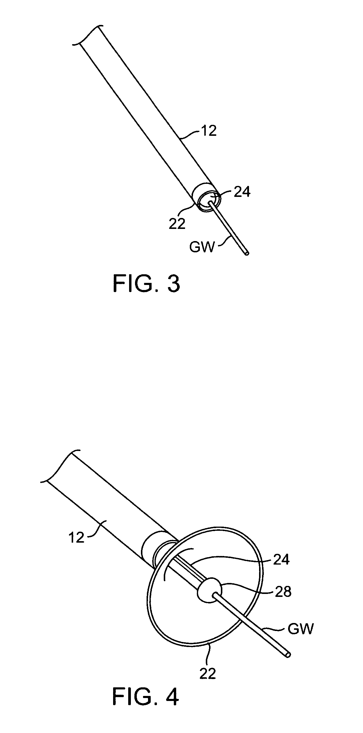
[0071] Treatment catheters 10 (FIG. 1) of the present invention typically comprise an elongate catheter body 12 that comprises a proximal end 14, a distal end 16, and one or more lumens 18, 20 (FIG. 2) within the catheter body. The distal end 16 may optionally comprise a suction housing 22 (FIGS. 4 and 5) that extends distally from the distal end of the catheter body 12 for isolating the leaflet during treatment as well as providing a debris evacuation path during treatment and protecting the vasculature from adverse embolic events. An energy transmission element 24 (e.g., a drive shaft, wire leads, or a waveguide-ultrasonic transmission element, or the like) may be positioned in one of the lumens in the elongate body 12 and will typically extend from the proximal end to the distal end of the catheter body. A handle 26 is coupled to the proximal end 14 of the elongate catheter body 12. A generator (e.g., RF generator, ultrasound generator, motor, o...


PUM


Abstract

The present invention provides devices and methods for decalcifying an aortic valve. The methods and devices of the present invention break up or obliterate calcific deposits in and around the aortic valve through application or removal of heat energy from the calcific deposits.

Description

CROSS-REFERENCES TO RELATED APPLICATIONS [0001] The present application claims the benefit and priority of U.S. Provisional Application Ser. No. 60 / 635,275, filed Dec. 9, 2004; U.S. Provisional Application Ser. No. 60 / 662,764 (Attorney Docket No. 020979-003200US), filed Mar. 16, 2005; and U.S. Provisional Application Ser. No. 60 / 698,297 (Attorney Docket No. 020979-003300US), filed on Jul. 11, 2005; the complete disclosures of which are expressly incorporated herein by reference.BACKGROUND OF THE INVENTION [0002] Aortic valve stenosis is a common cardiac disease resulting in approximately 65,000 aortic valve replacement surgeries in the United States annually. Aortic valve stenosis can occur via several etiologies including rheumatic disease, congenital and degenerative calcific stenosis. In developing countries, rheumatic fever results in thickening and progressive immobility of the valve tissues. Calcific disease accounts for almost all of the cases of aortic stenosis in the United...

Claims


Application Information

Patent Timeline
IPC IPC(8): A61M29/00
CPCA61B8/12A61N2007/0039A61B17/2202A61B17/221A61B17/320758A61B18/1492A61B18/18A61B2017/22038A61B2017/22061A61B2017/22069A61B2017/22079A61B2017/22098A61B2017/2215A61B2018/00011A61B2018/0022A61B2018/0262A61F2/2445A61M25/04A61M2025/105A61N7/022A61B17/22012A61B18/02
Inventor GIFFORD, HANSONDEEM, MARK E.BOYD, STEPHEN
Owner TWELVE
Why Eureka
Try Eureka